
AC relay using two photon couplers

The proposed circuit utilizes two H11C optically coupled silicon-controlled rectifiers (SCRs) arranged in a back-to-back configuration, which allows for bidirectional current control. This arrangement is particularly suitable for applications where the load current does not exceed 500 mA, making it ideal for low-power AC load switching.
In this design, the H11C components serve a dual purpose: they provide electrical isolation between the control and load sides while also facilitating the control of AC power. Each SCR is triggered by a control signal applied to its gate, allowing the relay to turn on and off in response to the control input. The back-to-back configuration ensures that the relay can handle both halves of the AC waveform, enabling it to conduct current in both directions.
The circuit typically consists of the following components:
1. Two H11C optically coupled SCRs, which are responsible for switching the AC load.
2. A control circuit that provides the gate trigger signals to the SCRs. This may include a microcontroller or a simple switch.
3. A load connected across the output terminals of the SCRs, which can be any AC device within the specified current rating.
4. Protective components such as snubber circuits or fuses may be included to safeguard against voltage spikes or overload conditions.
The simplicity of this solid-state relay design makes it an attractive option for various applications, including lighting control, motor control, and other low-power AC switching scenarios. The use of optically coupled SCRs enhances safety and reliability, as it prevents high-voltage AC from reaching the control side of the circuit.If load current requirements are relatively low (i.e. maximum forward rms current 500 mA), an ac solid state relay can be constructed quite simply by the connection of two H11C optically coupled SCRs in a back-to-back configuration as illustrated. An easy project.
Related Circuits
Upon purchasing the slave dial, it arrived without instructions, packaging, or additional details. The only visible markings, aside from decades of grime, were on the face (SMITH SECTRIC, ACELEC SYDNEY) and some markings on the bracket holding the mechanism...
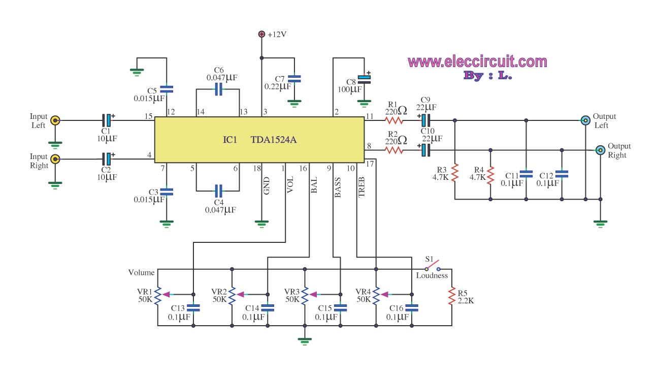
The stereo tone control circuit utilizes the integrated circuit TDA1524A. This IC serves as the central component in the design. The TDA1524A is a versatile integrated circuit designed for audio applications, particularly in tone control systems. It features a dual-channel...
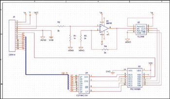
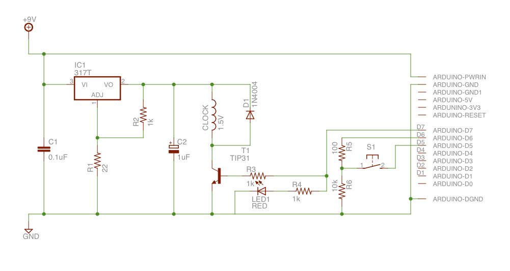
This example demonstrates the design of a circuit that incorporates both analog and digital components, features multiple power planes, and utilizes a single ground plane that is divided into analog and digital sections while maintaining a common reference point. The...
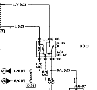
An automotive relay is being analyzed, which exhibits a more complex wiring configuration than typical relays. The diagram indicates that the B/G line maintains a high signal if certain conditions are met, specifically when the engine temperature is excessively...
Explore the power amplifier integrated circuit from National Semiconductor, the LM4780. What is noteworthy about this component is its very low harmonic distortion. Typically, manufacturers specify the maximum power of their products with a harmonic content of around 10%....
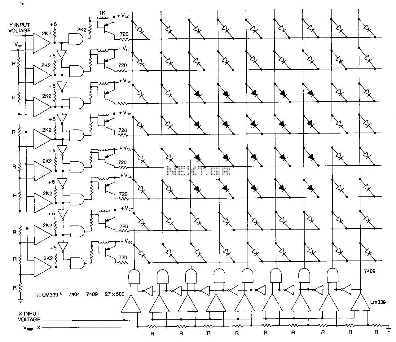
This matrix can display the values of two variables, such as frequency and voltage. The display consists of a graph made from a matrix of LEDs. The LEDs on each axis are color-coded: red indicates out of tolerance, while...