
Solar Panel Voltage Regulator Charger Circuit
The solar panel system operates through a series of interconnected components, each serving a specific role in the energy conversion and regulation process. At the heart of this setup, the photovoltaic cells capture sunlight and convert it into direct current (DC) electricity. The series configuration of the cells allows for higher voltage outputs, which is essential for efficient battery charging.
To enhance the system's efficiency, a solar tracker can be integrated. This mechanism adjusts the panel's orientation throughout the day, maximizing sunlight exposure and thereby increasing energy generation. Without tracking, the panel's performance can drop significantly, as the angle of sunlight changes with the time of day and weather conditions.
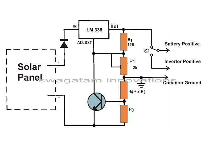
The voltage regulator circuit, utilizing the LM338 IC, is crucial for protecting the battery from overvoltage conditions. It ensures that the voltage supplied to the battery remains within safe limits, preventing damage to the battery and associated electronics. The use of a potentiometer allows for fine-tuning of the output voltage, accommodating different battery types and charging requirements.
The current control feature of the regulator circuit is equally important, as it maintains a steady charging current. This prevents the battery from being overcharged, which can lead to reduced lifespan or catastrophic failure. The design of the circuit allows for straightforward assembly, making it accessible for hobbyists and those looking to create their own solar power systems.
In summary, the solar panel system, with its photovoltaic cells, tracking capabilities, and voltage regulation, represents a comprehensive approach to harnessing solar energy. By ensuring stable voltage and current during the charging process, the system can operate efficiently and safely, providing a reliable source of renewable energy for various applications.We all know pretty well about solar panels and their functions. The basic functions of these amazing devices is to convert solar energy or sun light into electricity. Basically a solar panel is made up discrete sections of individual photo voltaic cells. Each of these cells are able to generate a tiny magnitude of electrical power, normally around 1. 5 to 3 volts. Many of these cells over the panel are wired in series so that the total effective voltage generated by the entire unit mounts up to an usable 12 volts or 24 volts outputs. The power generated from a solar panel is normally used for charging a lead acid battery. The lead acid battery when fully charged is used with an inverter for acquiring the required AC mains voltage for powering the house electrical.
Ideally the sun rays should be incident over the surface of the panel for it to function optimally. However since the sun is never still, the panel needs to track or follow the suns path constantly so that it generates electricity at an efficient rate. If you are interested to build an automatic dual tracker solar panel system you may refer one of my earlier articles.
Without a solar tracker, the solar panel will be able to do the conversions only at around 30 % efficiency. Coming back to our actual discussions about solar panels, this device may be considered the heart of the system as far converting solar energy into electricity is concerned, however the electricity generated requires a lot of dimensioning to be done before it can be used effectively in the preceding grid tie system.
The voltage acquired from a solar panel is never stable and varies drastically according to the position of the sun and intensity of the sun rays and of course on the degree of incidence over the solar panel. This voltage if fed to the battery for charging can cause harm and unnecessary heating of the battery and the associated electronics; therefore can be dangerous to the whole system.
In order to regulate the voltage from the solar panel normally a voltage regulator circuit is used in between the solar panel output and the battery input. This circuit makes sure that the voltage from the solar panel never exceeds the safe value required by the battery for charging.
Normally to get optimum results from the solar panel, the minimum voltage output from the panel should be higher than the required battery charging voltage, meaning even during adverse conditions when the sun rays are not sharp or optimum, the solar panel still should be able to generate a voltage more than say 12 volts which may be the battery voltage under charge. Solar Voltage regulators available in the market can be too costly and not so reliable; however making one such regulator at home using ordinary electronic components can be not only fun but also very economical.
A single IC LM 338 becomes the heart of the entire configuration and becomes responsibly for implementing the desired voltage regulations single handedly. The input is given to the shown input points of the IC and the output for the battery received at the output of the IC.
The pot or the preset is used to accurately set the voltage level that may be considered as the safe value for the battery. The circuit also offers a current control feature, which makes sure that the battery always receives a fixed predetermined charging current rate and is never over driven.
The module can be wired as directed in the diagram. The relevant positions indicated can be simply wired even by a layman. Rest of the function is taken care of by the regulator circuit. 🔗 External reference
Related Circuits
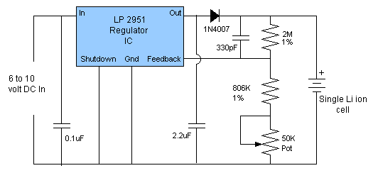
This article describes a circuit for a simple single-cell lithium-ion battery charger utilizing the LP2391 regulator IC. The circuit presented is designed for charging a single-cell lithium-ion battery efficiently. The LP2391 is a linear voltage regulator that provides a constant...
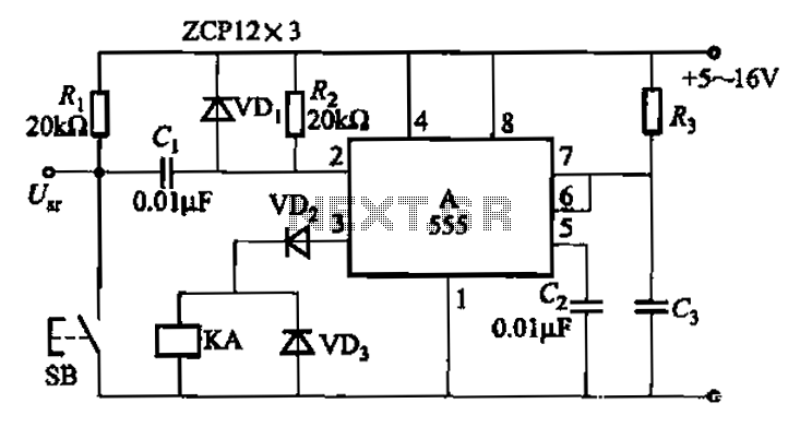
The 555 integrated circuit is utilized in a delay circuit configuration, functioning as a one-shot timer. The delay time can be adjusted using resistor R3 and capacitor C3. Typical values for R3 range from 1 kΩ to 10 MΩ,...
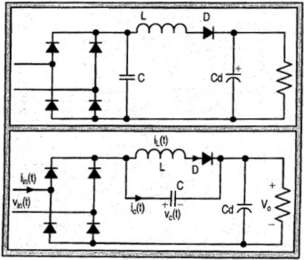
The input current for a passive power factor correction (PFC) circuit is not affected by variations in the output ripple, resulting in the need for a smaller inductance compared to earlier circuit designs. Passive power factor correction circuits are utilized...
The CD4538 is a dual Monostable Multivibrator. When triggered, the chip generates a single pulse or a high-low event. The T+ pin (pin 4) of U1a serves as the positive edge trigger input, while the T- pin (pin 5)...
The Digital Combination Lock Circuit is a schematic for a simple electronic combination lock utilizing the LS7220 integrated circuit (IC). This password-protected digital lock can activate a relay to control any device by entering a preset combination of four...
Professor Steven E. Jones' circuit demonstrates an 8x overunity. The concept of overunity refers to a system that produces more energy than is consumed, effectively achieving a coefficient of performance greater than one. In the context of Professor Steven E....