
Solent Radio Control Model Boat Club
The servo controller circuit is designed to enhance the performance of proportional servos in applications requiring precise and smooth motion control. The adjustment of the slew rate allows users to tailor the responsiveness of the servo to their specific needs, making it particularly useful in applications such as model boats where rapid movements can be undesirable. The use of a PICAXE microcontroller simplifies the design, allowing for a compact and efficient solution with minimal components. The bi-color LED serves multiple functions, providing real-time feedback on the servo's status and the operational mode of the controller. This feedback mechanism is crucial for users to monitor the performance and make necessary adjustments during operation. The design also considers potential issues such as signal loss, with built-in features to return the servo to a neutral position, enhancing reliability during use. Overall, the servo controller represents a significant advancement in servo control technology, offering flexibility and precision for hobbyists and professionals alike.A "servo slower" which has now evolved into a Servo Controller. `Servo slower` units are used to reduce the slew-rate (traverse time) of proportional servos. The most common use in model boats is to control the rotation of a servo-controlled gun turret, where trying to do so by transmitter stick movement alone results in unrealistically rapid and/or jerky motion. Using a `slower`, the stick can be thrust right or left and the servo will turn slowly and smoothly until it is aligned with the position commanded by the stick. The end to end travel time of the servo is adjustable in ten steps from `straight through` - ie the `slower` is inoperative - up to approximately 30 seconds.
Actual times will vary dependent upon the transmitter frame rate. Connections are via a flying-lead to the receiver and pcb mounted connector to the servo. This unit is based on a `PICAXE` micro-controller so all the clever stuff is done in software and as a result the parts count is minimal. The photo shows a prototype unit built on the readily available PICAXE project board AXE021 and the circuit diagram reflects that situation.
Should you wish to build the unit on strip-board then the 3. 5mm stereo jack socket (used to program the PIC over a serial link from your PC) can be omitted, together with the programming link LK1. If omitting the jack socket, R1 and R2 cannot be omitted - otherwise the serial input would `float` and the PICAXE could interpret that as a signal from the PC (which it expects to be attached to this input) to enter re-programming mode.
R1 and R2 can of course be replaced by a single 33K resistor. The white-ish looking LED is in fact a red/green bi-colour device which flickers at the transmitter frame rate to show the unit is operating. It flickers green whilst the servo is in alignment with the commanded position and flickers red whilst it is slewing to a new position.
In the case of the `straight through` mode being selected then the LED shows solid green. It also flashes red once per second if the input signal is not connected or disappears (eg a transmitter range problem) in either case returning the servo to its neutral position. The LED also gives a long red flash at each `step` position as the slew rate adjustment pot is turned from end to end, so by counting the flashes it is easy to determine the `slow` setting selected.
Click on the image to view the circuit diagram in a resizable pop-up window then enlarge, or maybe even maximize, the pop-up to render the diagram legible. The pop-up can be closed from its own control box, or alternatively click anywhere on the main window to close it.
The PICAXE 08M chip is used in preference to the more basic 08 part so that the internal oscillator can be set to 8Mhz operation, yielding a pulse-width resolution of 5 uSec which allows the 1 mSec traverse from end to end to be achieved in 200 steps resulting in very smooth operation. After checking for presence of the input signal the program enters the main loop where it first monitors the setting of the slew rate adjustment pot, diverting to the `straight through` mode if required.
The input pulse width (ie commanded servo position) is then checked and compared with the actual servo position. If an error exists, then the servo is moved one 5 uSec step towards the required postion and the program drops into the main loop again.
Thus after a number of steps at the transmitter`s (nominal) 20mSec frame rate the servo finally reaches the commanded position and the output pulse-width is then repeatedly asserted to hold the servo in position. The slew rate adjustment pot sets the number of times to go round the 20mSec main loop before incrementing/decrementing the servo position and in this manner quite long duration traverses can be achieved.
Each ti 🔗 External reference
Related Circuits
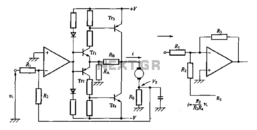
A discrete transistor current control circuit diagram. The discrete transistor current control circuit is designed to regulate the flow of current through a load by utilizing a transistor as the primary control element. This circuit typically consists of a few...
The UBA2021 can be utilized as a 600 V lamp controller and half-bridge driver integrated circuit (IC) for high-power applications. It is designed for long-life compact fluorescent lamp (CFL) and tubular fluorescent lamp (TL) applications. The UBA2021 is a versatile...
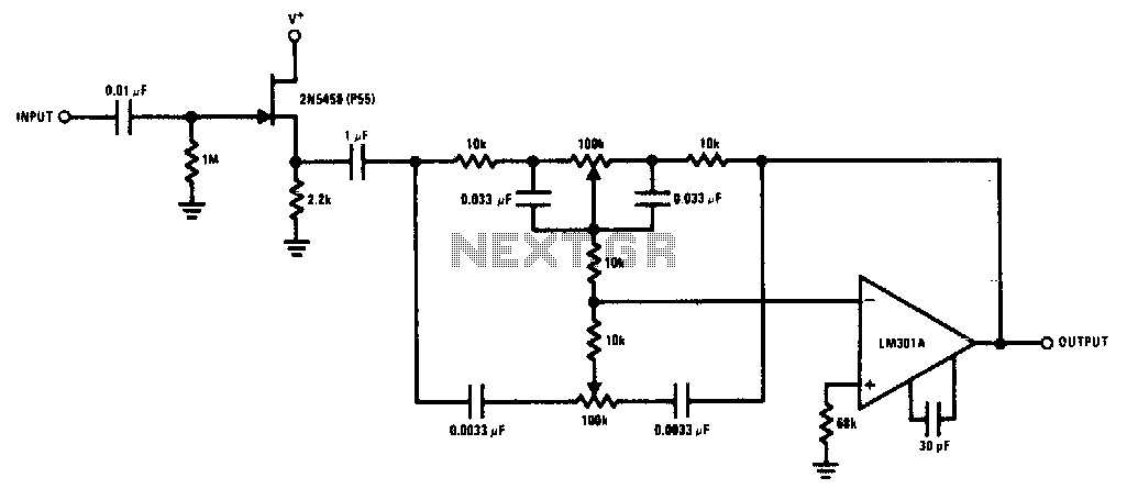
The 2N5458 JFET offers high input impedance and low noise characteristics, making it suitable for buffering an operational amplifier feedback tone control circuit. The 2N5458 is a Junction Field Effect Transistor (JFET) known for its superior electrical characteristics, particularly in...
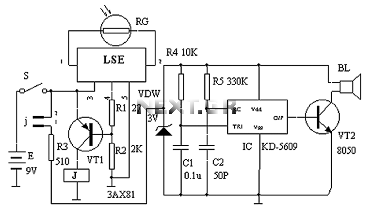
The circuit principle is illustrated in the accompanying figure. When the night light shines on the photosensitive resistor RG, it exhibits a high resistance (significantly greater than 50K). As a result, the output of the LSE pin is low,...
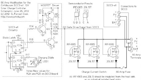
This circuit utilizes small switching transistors, with a maximum motor drive current limited to approximately 250 mA at 5V. Testing has been conducted across a voltage range from 3V to 21V, and with certain component modifications, it may be...
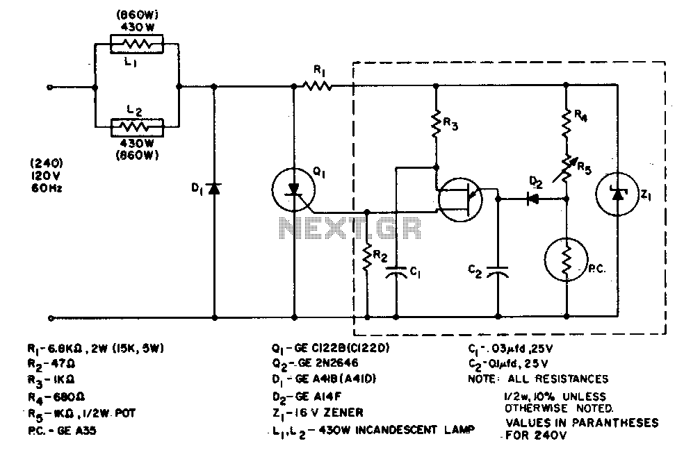
The system is designed to regulate an 860-watt lamp load from half to full power. This is achieved through the controlled half-plus-fixed half-wave phase control method. Applying half power to an incandescent lamp results in 30% of the full...