
Light control principle circuit rooster crows
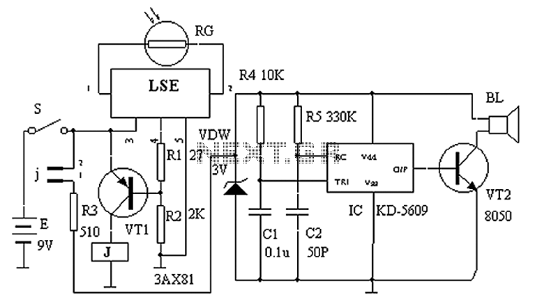
The described circuit operates as a light-sensitive activation system that controls sound output based on ambient light conditions. The core component, a photosensitive resistor (RG), is pivotal in determining the circuit’s response to light levels. During nighttime, RG maintains a high resistance, which keeps the output of the LSE pin low. This low output signals transistor VT1 to conduct, thereby energizing relay J. The relay's normally closed contacts open, effectively disconnecting power from the chicken sounds analog circuit IC KD5609, silencing the output.
As dawn approaches and light levels increase, the resistance of RG decreases significantly, reaching approximately 50K. This change triggers a transition in the LSE pin output to high, which turns off transistor VT1. The deactivation of VT1 allows relay J to return to its default state, closing its contacts. This closure restores power to the IC KD5609, activating the chicken sounds circuit. The result is an engaging auditory experience, with realistic chicken sounds produced through the speaker BL, thereby simulating a natural morning environment.
The circuit can be utilized in various applications, such as in educational projects, automated farm settings, or as a novelty alarm clock feature. Proper component selection is essential for ensuring that the photosensitive resistor and transistor can handle the expected ranges of light and current. Additionally, the relay must be rated to manage the load of the connected sound circuit. Overall, this light-activated circuit exemplifies a practical implementation of basic electronic principles to create an interactive and responsive system. Circuit principle is shown in FIG apparatus. When the night light irradiation on the photosensitive resistor RG, RG of great resistance, (much larger than 50K), so the LSE O, f eet equivalent open, LSEs pin output low, transistor VT1 conduction, excitation relay J pull its normally closed contacts j oFF, chicken sounds analog circuit IC KD5609 does not work without power. Once dawn, light irradiated on the RG, RG internal resistance becomes smaller ( 50K), this time the LSE pin output high, the transistor VT1 end, the relay J release, closes its contact j, analog sounds of chickens circuit energized work, accompanied by realistic sounds of chickens from the indicator in the speaker BL.
Related Circuits
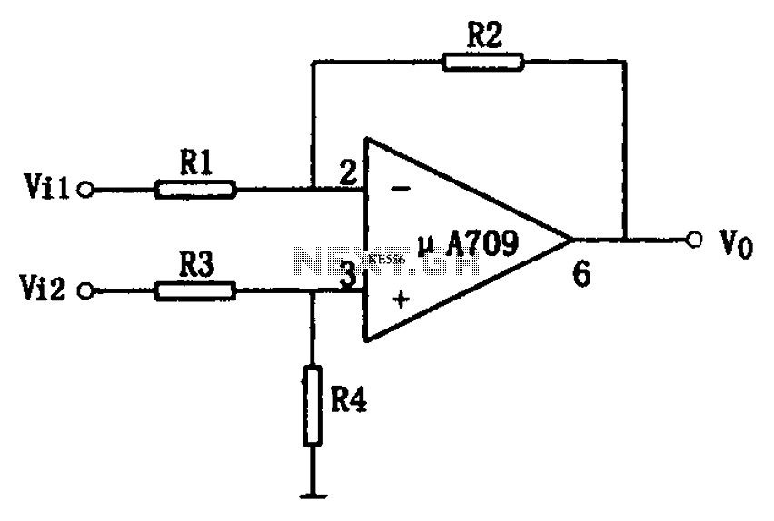
The simple differential amplifier circuit consists of two input signals, Vi1 and Vi2, which are connected through resistors R1, R3, and R4, forming a voltage divider circuit at the op-amp input. Vi1 is applied to the inverting input of...
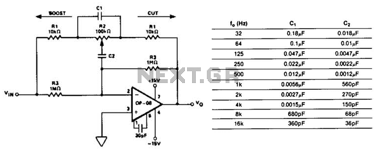
This circuit represents a section of an octave equalizer utilized in audio systems. The table outlines the values of C1 and C2 required to achieve specific center frequencies. This circuit can provide a boost or cut of 12 dB,...
The circuit described is a simple sound level meter, also known as a VU meter, which helps monitor sound levels to prevent hearing loss caused by loud music. It is a passive type of meter, requiring no separate power...
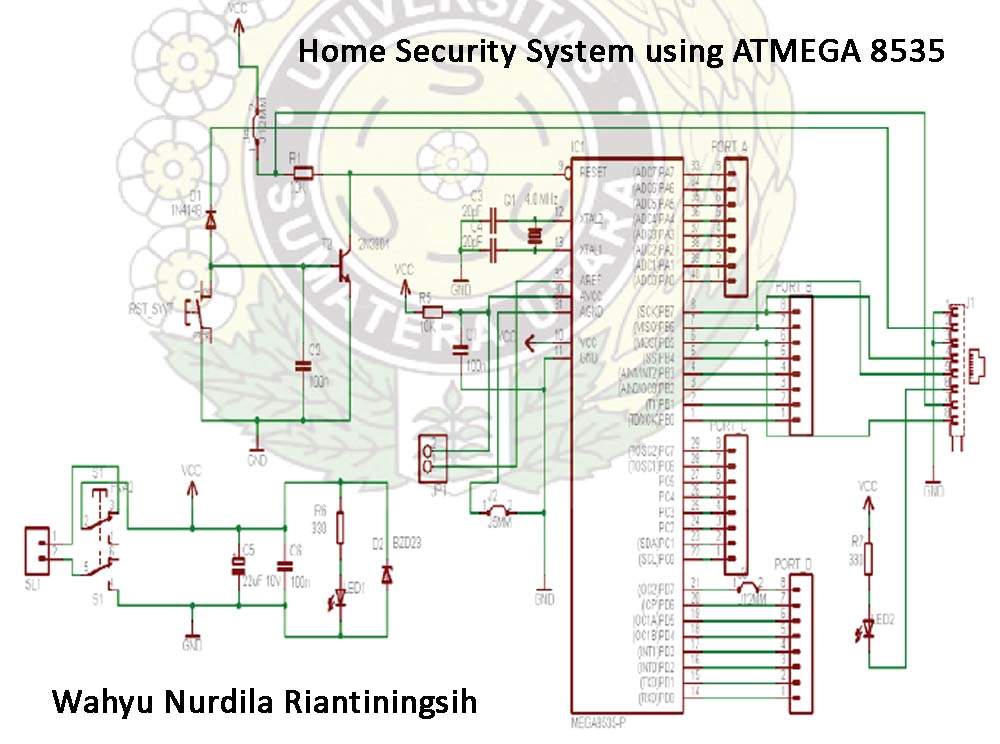
This document explains how to utilize an Arduino to control up to 12 servos simultaneously with minimal jitter. A straightforward serial interface allows for the control of the position of these 12 servo channels. Additionally, it is possible to...
The Atmega 8535 Color Conversion to Frequency project utilizes instrumentation technology to recognize colors, also known as a color sensor, which is essential in various industrial applications. This sensor has multiple uses, ranging from the paint industry to satellite...
A highly effective 1-watt FM transmitter circuit that is easy to construct. The circuit consists of four transistors: one functions as a stable oscillator, followed by a buffer stage to maintain frequency stability during adjustments. Next is a resonance...
Warning: include(partials/cookie-banner.php): Failed to open stream: Permission denied in /var/www/html/nextgr/view-circuit.php on line 713
Warning: include(): Failed opening 'partials/cookie-banner.php' for inclusion (include_path='.:/usr/share/php') in /var/www/html/nextgr/view-circuit.php on line 713