
solid state power controller

The circuit utilizes two 555 timer ICs, which are versatile components commonly employed in timing applications. U1 operates in astable mode, generating a square wave output. The frequency and duty cycle of this output are determined by the resistors and capacitors connected to the timer. In this configuration, the R4 potentiometer allows for real-time adjustments to the duty cycle, providing flexibility in the signal output.
The output from U1, which is a square wave signal, is fed into pin 4 of U2, serving as a reset input. This connection allows U2 to be triggered by the output of U1, enabling it to perform additional timing or control functions based on the modified duty cycle. The reset function of U2 can be utilized to synchronize its operation with the oscillations generated by U1, resulting in a compound functionality that can be applied in various electronic applications such as pulse width modulation, frequency modulation, or as part of a larger control system.
The overall design of this circuit allows for a wide range of applications, including LED dimming, motor speed control, and other scenarios where variable timing and control are essential. Proper component selection for the resistors and capacitors in conjunction with the 555 timers will ensure stable operation and desired performance characteristics.The ckt is built around two 555 timer ICs. U1 and U2. U1 is wired as a variable duty cycle oscillator with a constant time period of around 0.1 second. Duty cycle can be varied from 0 to 100 per cent by R4 potentiometer. The output of U1 (pin 3) is connected to the rest input (pin 4) of U2.. 🔗 External reference
Related Circuits
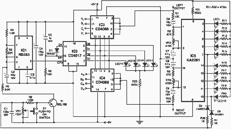
The add-on circuit presented here is useful for stereo systems. This circuit has provision for connecting stereo outputs from four different sources/channels as inputs and only one of them is selected/connected to the output at any one time. When...
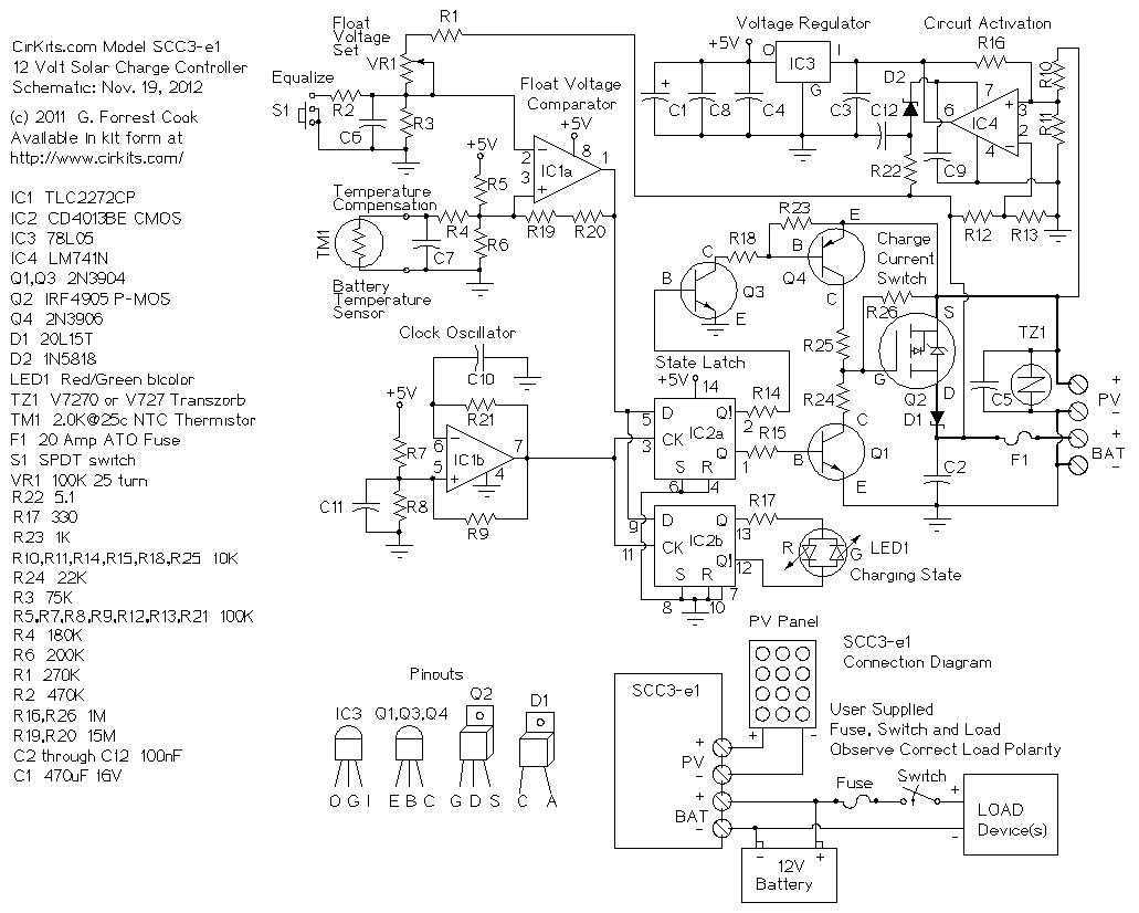
A 12 Volt solar power system can provide power to a wide variety of devices. Some examples include: lighting systems, cellular phones, CB and Ham radios, car stereos, televisions, recording equipment, fans, water pumps, and other low voltage DC...
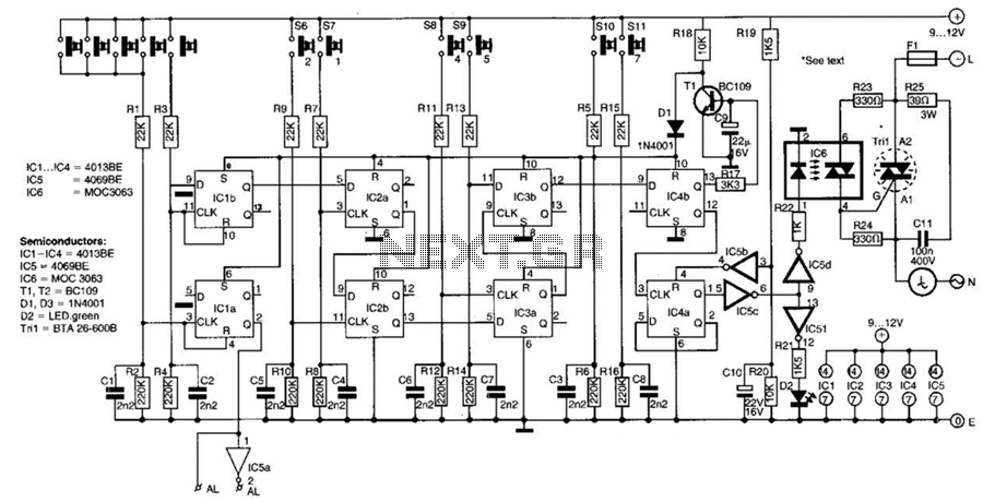
This switch utilizes four CD4013BE dual flip-flops, an inverter, and an optoisolator to control a triac, allowing it to switch a 25-A AC load current. A standard 4x3 telephone keypad is employed for entering a 6-digit code. In the...
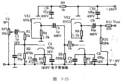
The FET amplifier is designed for enthusiasts who prefer tube sound but cannot utilize traditional tube amplifiers. It exhibits output characteristics similar to bipolar FET tube amplifiers, featuring good frequency response and sound quality comparable to tube amplifiers. Coupling...
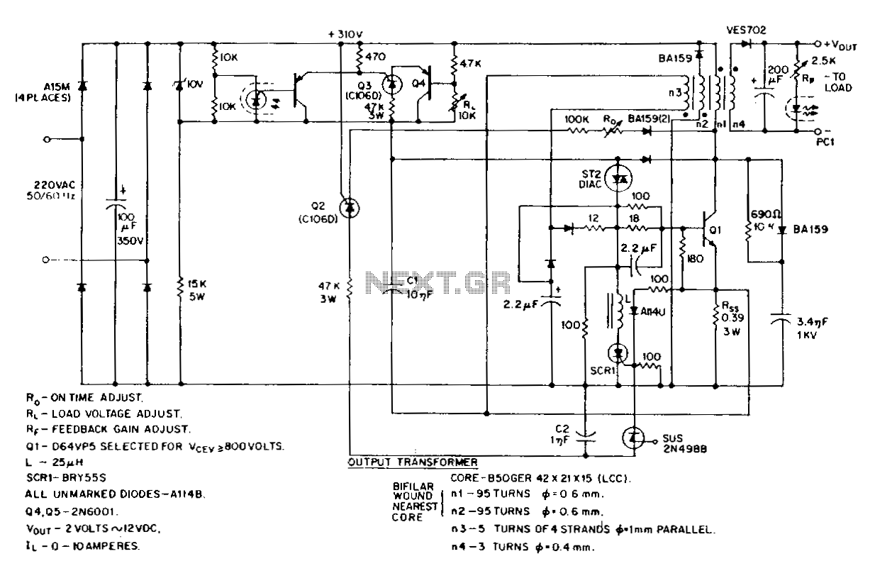
This low-voltage, high-current output switching power supply operates from a 220-V AC input. The circuit employs an ST2 diac relaxation oscillator, Q3, C1, and the diac to initiate conduction of the output switching transistor Q1. The on-time of Q1...
The following circuit illustrates a battery-powered burglar alarm sensor circuit. Features include foil tape and passive infrared sensors (PIRs), as well as magnetic reed contacts. This battery-powered burglar alarm sensor circuit is designed to provide an effective security solution for...