
Switching-power-supply
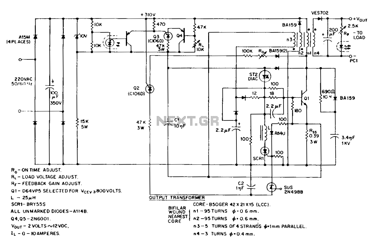
This circuit design represents a robust solution for converting high-voltage AC input into a stable low-voltage DC output suitable for high-current applications. The ST2 diac relaxation oscillator serves as the primary timing element, enabling precise control over the switching action of Q1, the output transistor. The timing network, inclusive of Q2, C2, R5, and SCR1, plays a critical role in maintaining the on-time duration of Q1, thereby influencing the overall output voltage through duty cycle modulation.
The incorporation of the H11C in a differential amplifier configuration enhances the circuit's ability to respond dynamically to variations in both input voltage and load conditions. This feedback mechanism is essential for maintaining output stability, ensuring that the power supply can adapt to changes in the load without compromising performance. The galvanically isolated feedback loop further protects sensitive components from fluctuations, enhancing reliability.
The use of high-voltage thyristors rated at 400V V_RRM is notable, as these components are designed to handle significant voltage levels while providing reliable switching capabilities. Their role as PNP remote-base transistors allows for effective control within the circuit, facilitating the necessary switching actions without introducing excessive power loss.
Short-circuit protection is a critical feature of this design, implemented through the feedback of the collector current from Q1 into the turn-off circuitry via R5. This mechanism ensures that in the event of a short circuit, the circuit can quickly respond to prevent damage to the components, thereby enhancing the durability and safety of the overall power supply system.
In summary, this low-voltage high-current switching power supply circuit exemplifies advanced design techniques to achieve stability, efficiency, and protection, making it suitable for a variety of demanding applications.This low-voltage high-current output, sWitching de power supply is running off the 220-Vac input. In this circuit, an ST2 diac relaxation oscillator, Q3, Cl, and the diac, initiates conduction of the output switching transistor Ql, the on-time of which is maintained constant by a separate tirning/conunutation network consisting of Q2, C2, SUS, and SCR 1. The output voltage, consequently, is dependent on the duty cycle. To compensate for unwanted variations of output voltage because of input voltage or load resistance fluctuations, an HllC wired as a linear-model unilateral PNP transistor in a stable differential amplifier configuration is connected into the galvanically isolated negative-feedback loop. The loop determines the duty cycle and hence the output voltage. Of further interest in this circuit is the use of several low-current, high-voltage, 400V VvRM thyristors (Q2, Q3,) which are also used as pnp remote-base transistors.
Short-circuit protection is assured by coupling Ql collector-current feedback into the tum-off circuitry via Rss· 🔗 External reference
Related Circuits
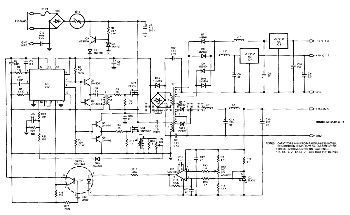
The power supply employs two VN4000A 400-V MOSPOWER FETs configured in a half-bridge arrangement. It provides outputs of +5 V at 20 A and ±15 V (or ±12 V) at 1 A. The low-current outputs utilize linear three-terminal regulators,...
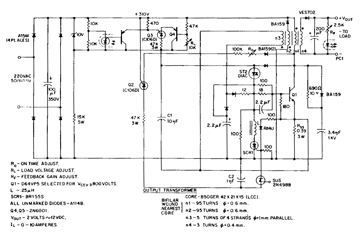
This low-voltage, high-current output switching power supply operates from a 220 VAC input. In this circuit, an ST2 diac relaxation oscillator, along with Q3, C1, and the diac, initiates the conduction of the output switching transistor Q1. The on-time...
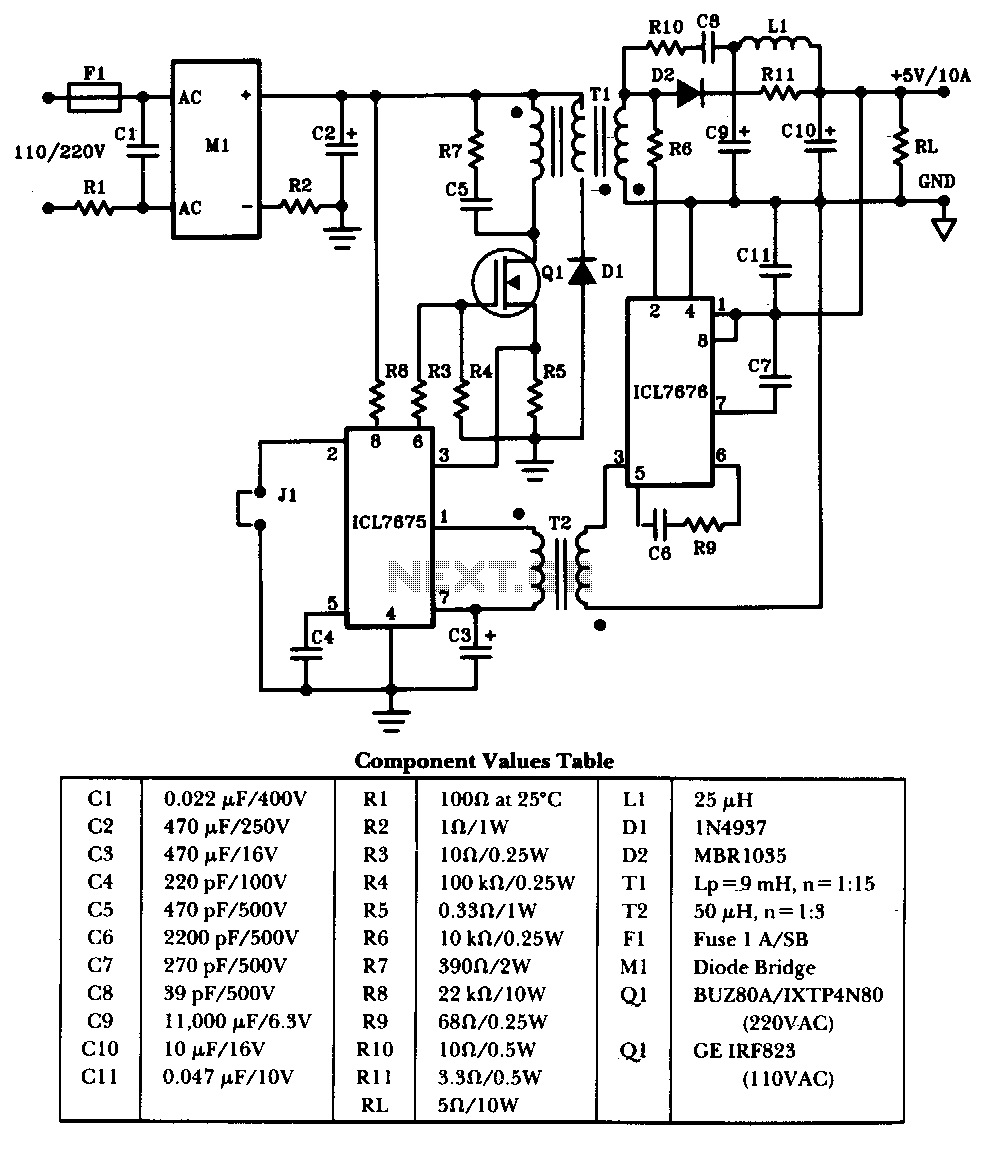
The schematic illustrates a 50W power supply providing a 5V, 10A output. It operates as a flyback converter in continuous mode. The circuit incorporates both primary and secondary side controllers, offering full protection against fault conditions such as overcurrent....