
Solid State Relay
The Solid State Relay (SSR) Switch described is designed for efficient control of high-power circuits using low-power signals. The primary function of this relay is to provide electrical isolation between the control circuit and the high-power load, ensuring safe operation and protecting sensitive components from high voltages.
This SSR operates within a voltage range of 24 to 240 VAC, capable of handling loads up to 500 watts. The triggering mechanism requires a control voltage of 2 to 5 VDC, which corresponds to TTL (Transistor-Transistor Logic) levels, allowing it to interface easily with microcontrollers and other low-power devices. The input current requirement for triggering is 10 mA, making it suitable for interfacing with various control systems without excessive power consumption.
An optocoupler is integrated into the design to ensure electrical isolation between the input and output, enhancing safety and reliability. The use of an optocoupler prevents high voltage from affecting the control side of the circuit, which is critical in applications where sensitive electronics are involved.
The relay features a Power Battery Terminal (PBT) for straightforward connection to the 230 VAC mains supply, facilitating the installation process. Additionally, terminal pins are provided for connecting the input trigger signal, allowing for flexible wiring options based on the specific application requirements.
Heat dissipation is managed through the inclusion of a heatsink for the TRIAC, which is the primary switching component in this SSR. The heatsink is essential for maintaining optimal operating temperatures, thereby prolonging the life of the relay and ensuring consistent performance under load.
For mounting convenience, the PCB is designed with four mounting holes, each measuring 3.2 mm. This allows for secure installation in various enclosures or on mounting surfaces. The dimensions of the PCB are compact, measuring 29 mm by 74 mm, making it suitable for applications with space constraints.
Overall, this Solid State Relay Switch kit is an effective solution for controlling high-power devices with low-power signals, combining safety, efficiency, and ease of use in its design.Solid State Relay Switch is a simple kit which will help you control (ON / OFF) a single high power circuit from a low power drive. Load - 24 to 240 VAC @ 500 W. Trigger voltage - 2 to 5 VDC (TTL) @ 10 mA. Input isolated with use of Optocoupler. Power Battery Terminal (PBT) for easy input 230 VAC mains and load connection. Terminal pins for connecting input trigger signal. Heatsink for TRIAC. Four mounting holes of 3.2 mm each. PCB dimensions 29 mm x 74 mm 🔗 External reference
Related Circuits
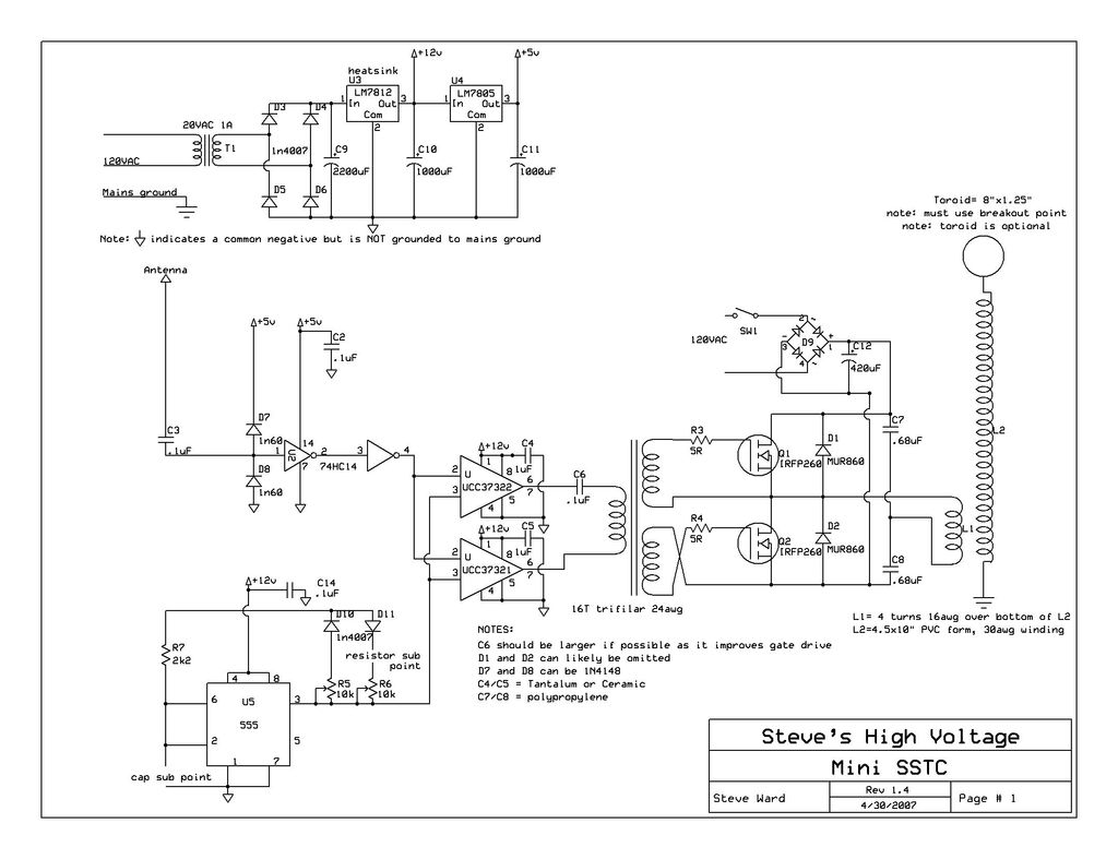
This instructable provides detailed instructions for constructing a solid-state Tesla coil based on Steve Ward's mini SSTC schematic. The solid-state Tesla coil (SSTC) is an advanced high-frequency resonant transformer that operates without the need for mechanical components such as spark...
The aquarium design utilizes a DPDT relay and a 12V inverter. The selected relay is rated adequately for a 400-watt load. The 12V DC relay, transformer, and diodes consume minimal power, making efficiency a minor concern. It is unclear...
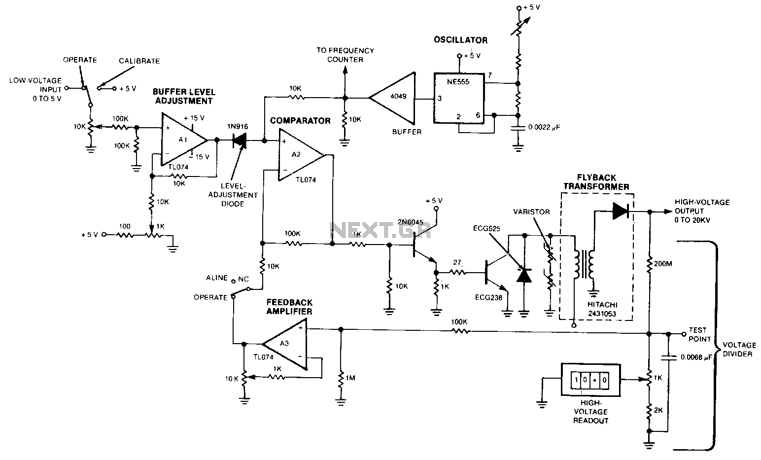
The output voltage varies approximately linearly up to 20 kV as the input voltage is adjusted from 0 to 5 V. A 5-0 potentiometer is used to tune the oscillator, optimizing the output voltage at the frequency of maximum...
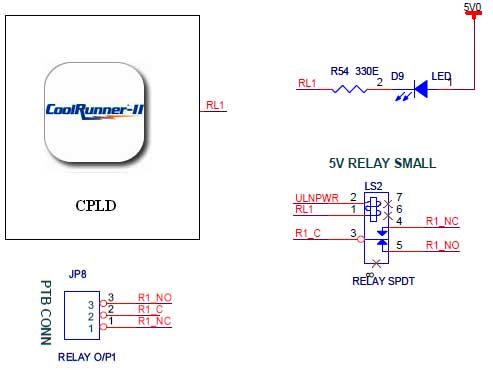
The CoolRunner-II board features external 5V relay interfacing, as indicated in the accompanying figure. The ULN2803 is utilized as a driver for the CPLD I/O lines, with the driver outputs connected to the relay modules. A PTB connector is...
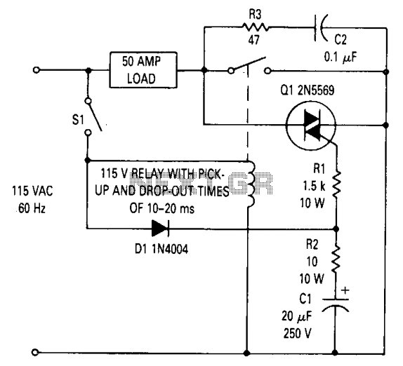
This circuit can be utilized to prevent relay contact arcing for loads up to 50 amperes. A delay exists between the moment a relay coil is energized and when the contacts close, as well as a delay from when...
Below are three examples of controlling a relay from the PC's parallel printer port (LPT1 or LPT2). Figure A shows a solid state relay controlled by one of the parallel port data lines (D0-D7) using a 300 ohm resistor...