
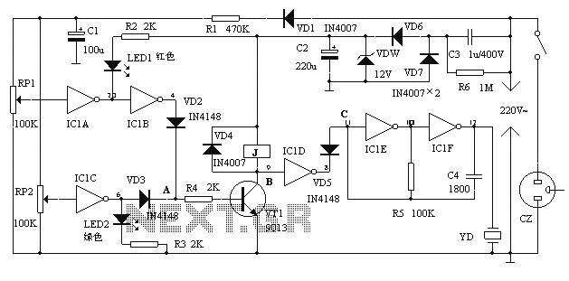
Triac relay-contact protection
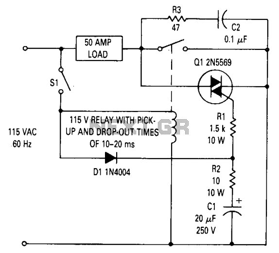
This circuit design effectively mitigates the issue of contact arcing in relay systems handling substantial loads. It employs a TRIAC, which is a semiconductor device capable of controlling current flow, positioned strategically across the relay contacts. The operational sequence begins when switch SI is closed, initiating the energization of the relay coil. The relay contacts will not close immediately due to the inherent delay of approximately 15 ms, allowing the TRIAC to activate beforehand, thus preventing any arcing that could damage the contacts.
The circuit operates on an alternating current (AC) supply, where the TRIAC's activation is contingent upon the polarity of the voltage. During the negative half cycle of the AC waveform, the TRIAC remains inactive. However, as the voltage reaches a positive peak, diode D1 becomes forward-biased, allowing current to flow through resistor R1, which provides the necessary gate current to turn on the TRIAC. This ensures that the TRIAC is fully activated before the relay contacts close, thereby allowing the load current to flow through the contacts instead of the TRIAC.
The design also considers the maximum delay before the TRIAC turns on, which can be calculated based on the supply frequency. For a 60 Hz AC supply, this delay can be up to 5-6 ms. This timing is critical, as it guarantees that the TRIAC will be conducting before the relay contacts engage, thus effectively eliminating the potential for contact arcing and extending the lifespan of the relay components. Overall, this circuit configuration provides a reliable solution for applications requiring high current relay operation without the detrimental effects of arcing.This circuit can be used to prevent relay contact arcing for loads up to 50 amperes. There is some delay between the time a relay coil is energized and the time the contacts close. There is also a delay between the time the coil is de-energized and the time the contacts open. For the relay used in this circuit both times are about 15 ms. The TRIAC across the relay contacts will turn on as soon as sufficient gate current is present to fire it. This occurs after switch SI is closed but before the relay contacts close. When the contacts close, the load current passes through them, rather than through the TRIAC, even though the TRIAC is receiving gate current. If SI should be closed during the negative half cycle of the ac line, the TRIAC will not turn on immediately but will wait until the voltage begins to go positive, at which time diode Dl conducts providing gate current through Rl.
The maximum time that could elapse before the TRIAC turns on is S-Vi ms for the 60 Hz supply. This is adequate to ensure that the TRIAC will be on before the relay contact closes. 🔗 External reference
Related Circuits
A low-pass filter is a stable state-space system that has an input and produces an output. If the input is a quasi-periodic signal, the output will be the same quasi-periodic signal with a phase shift. The key difference is...
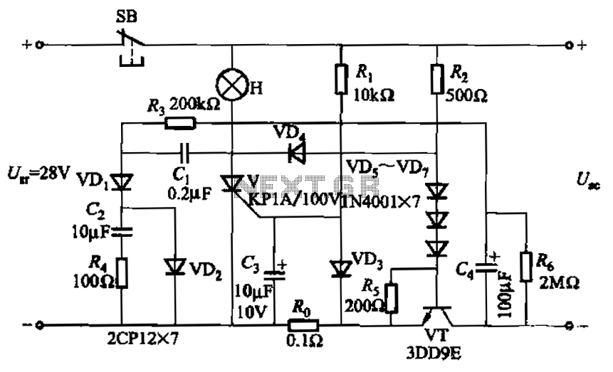
Capacitor C3 is used to determine the cutoff power, specifically the voltage threshold (VT cutoff), which influences the delay time selection. The schematic includes a reset button, SB, that is utilized to reset the system after a failure has...
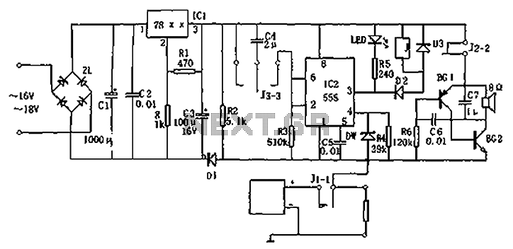
Circuit diagram for a DC power supply protection circuit. The device includes a buck rectifier power supply, a monostable delay circuit, a relay control circuit, and an audio feedback oscillation circuit. The entire circuit operates with a DC voltage...
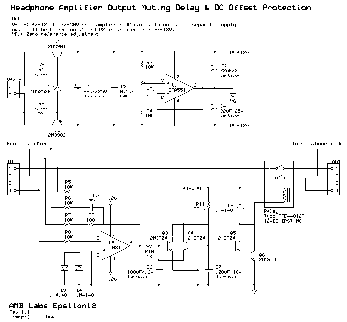
The circuit integrates several functions, including a smooth startup for the AC power line, with a one-second delay before connecting to the power supply transformers of the amplifier through relay RL1 and resistor Rx. This delay is designed to...
The alarm protection can trigger a sound and light alert when the mains voltage exceeds or falls below a predetermined threshold. It automatically disconnects the electrical power supply without damaging the electrical protection. The device is compact, fully featured,...
RS-232C serial port lines are quite prone to be damaged by overvoltages. The damage to computer serial ports has become more and more expensive to replace because of higher integration: usually, you have to buy a new motherboard if...