
Sound-activated-switch
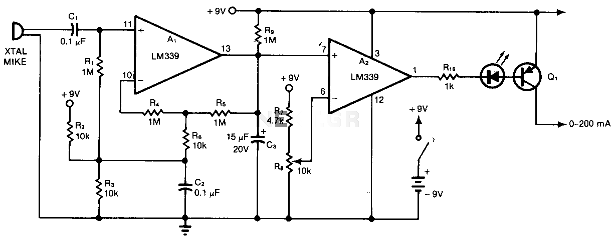
Al and A2 are two sections of a quad comparator. The first section, Al, functions as an amplifier and detector. Resistors R5 and R6 set the gain at 100; the output of Al is an open collector to negative-peak-rectify the output with a decay time constant determined by R9 and C3. This output is then compared with the reference level selected by R7. A2 triggers switch Q1, and an LED inserted in the base drive of Q1 provides a visual indication of switch closure. The standby battery drain is 2 mA. Use potentiometer R8 to select the desired sensitivity.
Al and A2 are integral components of a quad comparator configuration, where Al operates as an amplifier and detector circuit. The gain of the amplifier is established by resistors R5 and R6, which are configured to provide a gain factor of 100. The output from Al is designed as an open-collector output, enabling it to perform negative peak rectification. The decay time constant of this output is influenced by the combination of resistor R9 and capacitor C3, which together determine how quickly the output voltage will decay after the peak is reached.
The output from Al is subsequently compared to a reference voltage set by resistor R7, allowing for precise detection of signal levels. The comparator's second section, A2, is responsible for triggering a switch, specifically Q1. When the conditions are met, Q1 closes, and an LED connected to the base of Q1 illuminates, providing a clear visual indication that the switch has been activated.
The circuit is designed to maintain a low standby current drain of 2 mA, optimizing battery life during periods of inactivity. Additionally, the sensitivity of the circuit can be adjusted using potentiometer R8, allowing for user-defined thresholds for detection. This flexibility is crucial for applications requiring fine-tuning based on varying signal conditions or environmental factors. Overall, this quad comparator configuration is well-suited for applications needing precise signal amplification, detection, and visual feedback.Al and A2 are two sections of a quad comparator. The first, Al, functions as an amplifier and detector. Resistors R~and R6 set the gain at 100; the output of Al is an open collector to negative-peak-rectify the output with a decay time constant determined by R9 and C3. This de output is then compared with the reference level selected by RB. A2 triggers switch Ql, and an LED inserted in the base drive of Ql gives visual indication of switch closure. The standby battery drain is 2 mA. Use potentiometer R8 to select the desired sensitivity. 🔗 External reference
Related Circuits
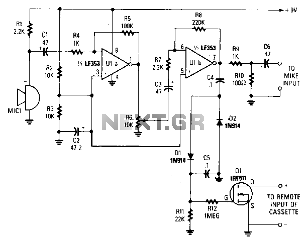
A sensitive electret microphone captures sound and transmits the signal to a two-stage amplifier circuit, comprising Ula and Ulb. The amplified output from Ulb is directed to a voltage-doubler circuit (consisting of D1, D2, C4, and C5). The output...