
Sound-activated-switch
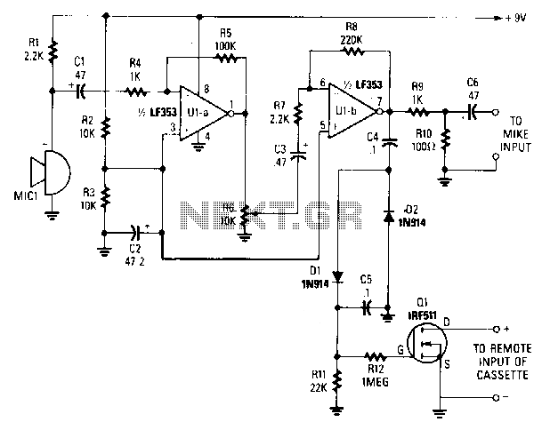
A sensitive electret microphone captures sound and transmits the signal to a two-stage amplifier circuit, comprising Ula and Ulb. The amplified output from Ulb is directed to a voltage-doubler circuit (consisting of D1, D2, C4, and C5). The output from the doubler is fed into the gate of Q1. When the DC voltage at the gate reaches the threshold level, Q1 activates, initiating the recorder. Resistor R6 adjusts the circuit's sensitivity and should be fine-tuned for optimal performance.
An electret microphone serves as the initial sound transducer in this circuit, converting acoustic energy into an electrical signal. The two-stage amplifier circuit, consisting of operational amplifiers Ula and Ulb, enhances the weak signal from the microphone to a more manageable level. The design ensures that the output from Ulb is sufficiently amplified to drive subsequent stages of the circuit.
Following amplification, the signal is processed by a voltage-doubler circuit, which typically uses diodes (D1 and D2) and capacitors (C4 and C5) to increase the voltage level. This step is crucial for ensuring that the signal reaches the appropriate voltage necessary to control the gate of transistor Q1. The voltage-doubling configuration allows for a more robust signal that can effectively switch the transistor on.
Transistor Q1 functions as a switch in this configuration. Once the voltage at its gate exceeds the threshold, Q1 transitions from the off state to the on state, thereby initiating the recording process. This action is pivotal for applications requiring sound activation, such as voice-activated recorders.
Resistor R6 plays a critical role in determining the sensitivity of the microphone circuit. By adjusting the resistance value, one can fine-tune the voltage level required to switch Q1 on, allowing for greater flexibility in the circuit's response to varying sound levels. Experimentation with R6 is essential to achieve optimal sensitivity, ensuring reliable operation in diverse acoustic environments.
Overall, this circuit design exemplifies a straightforward yet effective approach to sound activation, leveraging basic electronic components to create a responsive recording device.A sensitive electret microphone picks up the sound and feeds the signal to a two-stage amplifier circuit, consisting of Ula and Ulb. The amplified output of Ulb is fed ·to a voltage-doubler circuit (comprised of Dl, D2, C4, and C5).
The output of the doubler is input to the gate of Ql. When the de voltage reaches the gate"s threshold level, Ql switches on, starting the recorder. Resistor R6 sets the circuit"s sensitivity and should be experimented with to obtain the optimum adjustment. 🔗 External reference
Related Circuits
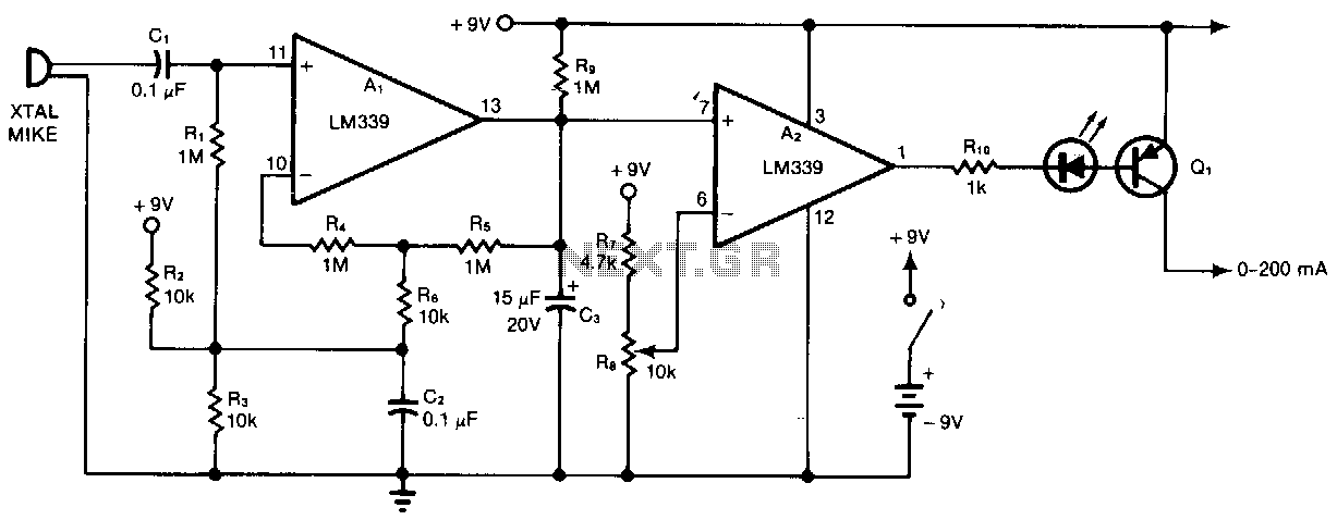
Al and A2 are two sections of a quad comparator. The first section, Al, functions as an amplifier and detector. Resistors R5 and R6 set the gain at 100; the output of Al is an open collector to negative-peak-rectify...