
Sound effects generator
The circuit is designed to produce a variety of audio outputs through the modulation of frequencies, making it versatile for different applications. The binary counter, likely implemented using a standard counter IC, serves to generate a sequence of binary values that control the D/A converter. The D/A converter translates these binary values into corresponding voltage levels that modulate the VCO. The VCO generates a waveform whose frequency is proportional to the control voltage it receives, allowing for a dynamic range of sound frequencies.
The timing network associated with the VCO is critical for determining the oscillation characteristics. The combination of diodes, capacitors, and resistors in this network shapes the waveform and affects the frequency response. The use of a potentiometer (R11) allows for user adjustment of the initial frequency, providing flexibility in sound generation.
The audio output amplifier enhances the signal from the VCO, ensuring that the sound produced is loud enough for practical applications such as alarms or alerts. The parallel configuration of the buffer amplifier gates ensures that the output signal is robust and can drive speakers or other audio output devices effectively.
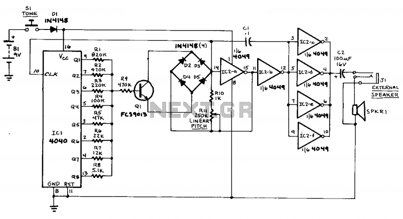
Overall, this circuit showcases a practical application of digital and analog components to generate a variety of sound effects, demonstrating the integration of different electronic principles to achieve a versatile audio output system.This circuit can generate a European police-car siren, bird noises, spaceship sounds, etc. In addition, it can be put to use as a doorbell, an alarm, etc. The circuit consists of four parts: a binary counter, a D/A converter, a VCO, and an audio output amplifier. The initial frequency of oscillation is determined by potentiometer Rll. The VCO first oscillates at a relatively low frequency, and gradually picks up speed as the control voltage supplied by the D/A converter increases.
The D/A converter is the group of resistors R1-R8. When none of ICl's outputs is active, little current will flow into the base of Ql, so the VCO's control voltage will be low. As more and more counter outputs become active, base cutrent increases,and thereby so does the VCO's frequency of oscillation.
The VCO itself is composed of IC2-a, IC2-b, Ql, and the timing network comprisingD1-D4, Cl, RIO, and Rll. The buffer amplifier is made up of the four remaining gates from IC2, all wired in parallel. 🔗 External reference
Related Circuits
The simplest way to harness free available energy is by utilizing solar cells. A single efficient solar cell, when paired with a well-configured HHO generator, can produce a significant amount of gas suitable for various applications, all without incurring...
The first timer is used as a monostable and determines the tone duration when triggered by a positive pulse at pin 6. The second timer is enabled by the high output of the monostable. It is connected as an...
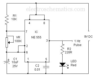
A simple buzzer is being converted into an oscillating buzzer to produce a sound similar to that of an automobile's reverse indicator. The schematic provided is borrowed from electroschematics.com. The intention is to replace the LED in the circuit...
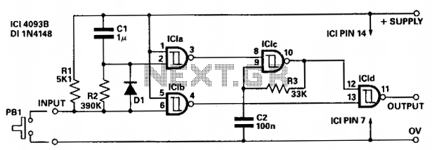
The circuit provides independent control of the initial delay and pulse rate. ICIc functions as a pulse generator, with its operation inhibited by the normally low output of ICla. When the circuit input transitions to low (e.g., when pressing...
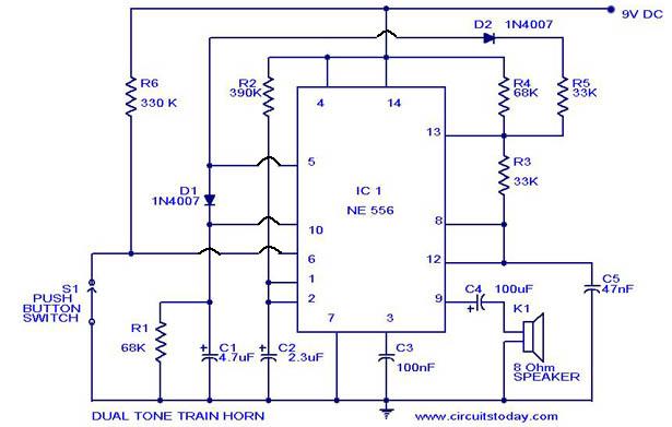
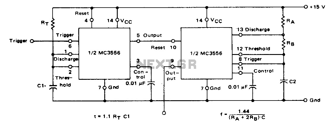
A dual-tone model train horn/sound generator/simulator circuit can be created using two NE 555 timers connected in cascade. However, the circuit diagram presented is designed with the NE 556 integrated circuit, which essentially comprises two 555 timers in a...
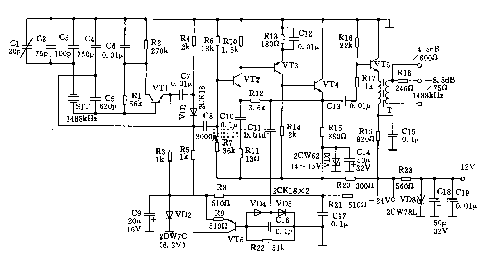
A 1488 kHz master oscillator quartz crystal resonator is utilized for frequency stabilization. The output from the frequency divider provides three different square wave signal outputs at 4 kHz, 12 kHz, and 124 kHz. The circuit includes transistors VT1,...