
555 1 Hz pulse generator

The circuit utilizes a 555 timer in astable mode to generate a square wave output that drives the buzzer. The 555 timer is configured with resistors R1 and R2, and a timing capacitor C1, which together determine the frequency and duty cycle of the output waveform. The frequency of oscillation can be calculated using the formula:
\[ f = \frac{1.44}{(R1 + 2 \cdot R2) \cdot C1} \]
Where \( f \) is the frequency in Hertz, \( R1 \) and \( R2 \) are in ohms, and \( C1 \) is in farads. A variable resistor (potentiometer) can be used for R1 to allow fine-tuning of the duty cycle, which is essential for achieving the desired sound characteristics of the buzzer.
The buzzer should be connected to the output pin of the 555 timer, ensuring that the current drawn by the buzzer does not exceed the output current capability of the timer, typically around 200 mA. If the buzzer requires more current, a small NPN transistor, such as the 2N3904, can be employed to switch the buzzer. The base of the transistor would be connected to the output pin of the 555 timer through a current-limiting resistor, while the buzzer would be connected to the collector of the transistor, with the emitter grounded.
For applications requiring additional amplification, it is advisable to place the amplifier circuit after the 555 timer. This configuration allows the timer to control the amplifier, ensuring that the amplified signal can drive the buzzer effectively without overloading the 555 timer. Proper attention to component ratings and circuit layout will ensure reliable operation and desired sound output from the buzzer circuit.A simple buzzer to convert to an oscillating buzzer so as to obtain the sound similar to that of an automobile`s reverse indicator. I`ve posted a schematic(borrowed from electroschematics. com) below. I intent to replace the LED with my buzzer and omit the resistor. I hope by building this circuit, to make my buzzer `buzz`(or make noise) at an interval of 1 second(since its a 1
Hz pulse generator). Would the results be similar to my needs Thank you Steve. I had checked for its current requirements but the device came in a black plastic containment with nothing marked on it. I am not sure of its current requirements and hence decided to omit the resistor to prevent any shortage.
Since its a buzzer that runs on a wide range of voltage input(3 volts-12 volts), I figured a bit too much current wouldn`t be a problem either. It will be a problem for the 555 ! It can`t supply an infinite amount of power. You MIGHT get away with just the chip. Measure the current of the buzzer on your bench. There are EQUATONS to calculate the resistors for desired output, but I bypassed those many years ago and just did experiments to determine aproximate value for the charging capacitor to get desired output.
Here are my results: Also, for the values of resistors R1 and VR can effect the DUTY-CYCLE. That is the ratio of ON-TIME to the OFF-TIME of the waveform. If the thing you build seems to pulse at ONE second, but it is only a quick "ON-PULSE" then the OFF PULSE seems to last a lot longer. you need to place a variable resistor in place of the R1 resistor and adjust the two variable resistors untill you get the desired DUTY-CYCLE.
The 555 circuit you are building will put out a one second pulse, but will not make the TONE you want to hear. But you say you are using a BUZZER for that or just lighting an LED. Be sure the current drain of the buzzer is not more than the amperes available from the 555 timer (which isn`t much).
You may have to make the 555 output drive a small general transistor like a 2n3904 which will power the buzzer. And hey, If I had to add an additional amplifier for the buzzer, should it go before the 555 timer or after.
I think it should be before the timer but correct me if I`m wrong 🔗 External reference
Related Circuits
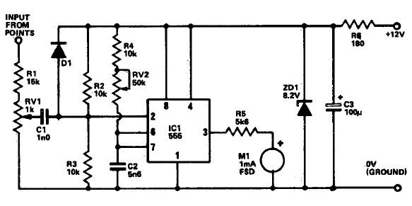
The following circuit illustrates a Tachometer Circuit Project. This circuit is constructed using the 555 Timer IC. Features include a monostable IC and voltage capabilities. The Tachometer Circuit utilizes a 555 Timer configured in monostable mode to measure the rotational...
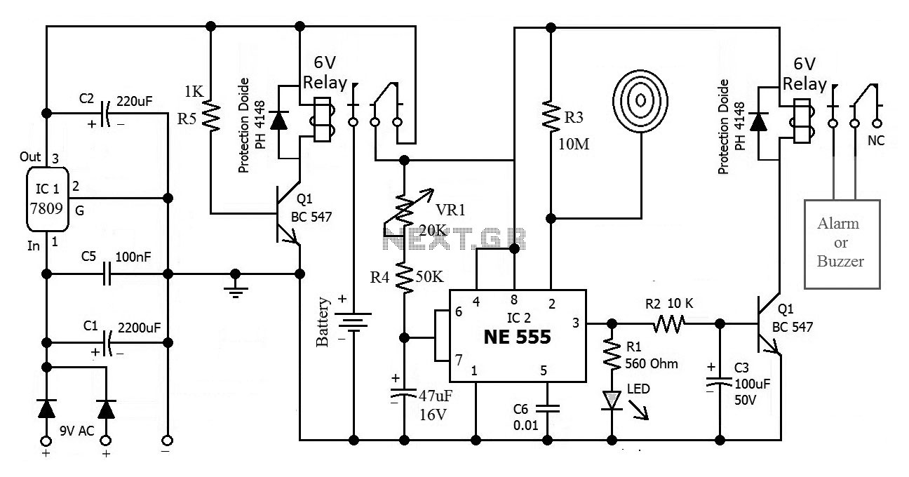
This is the circuit diagram of a touch-activated alarm system that remains operational during power outages. The alarm system is triggered when someone touches the designated touch plate. A notable feature of this circuit is the automatic battery activator,...
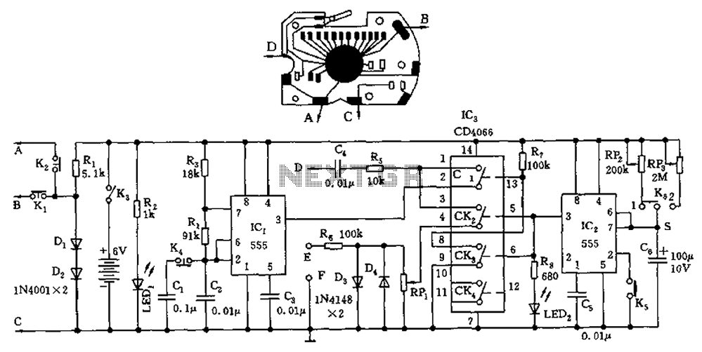
A circuit utilizing a standard digital quartz electronic watch, with its crystal soldered, forms a digital frequency meter as illustrated by the connected circuit. The test signal is applied to the E and F sides via components such as...
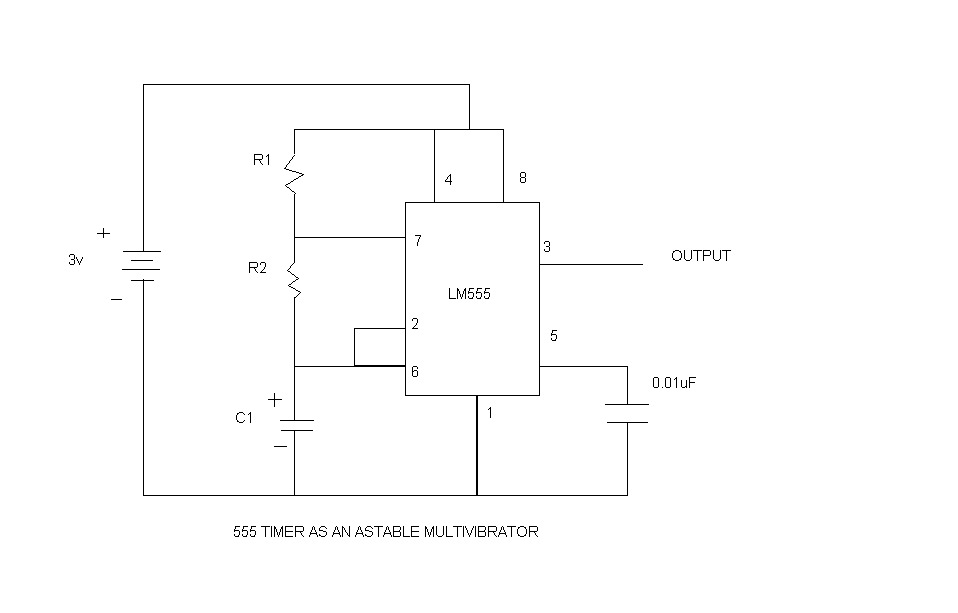
An astable multivibrator, commonly referred to as a free-running multivibrator, is a circuit that generates rectangular waves without the need for external triggering. The timing characteristics of this circuit are determined by the values of the resistors and capacitors...
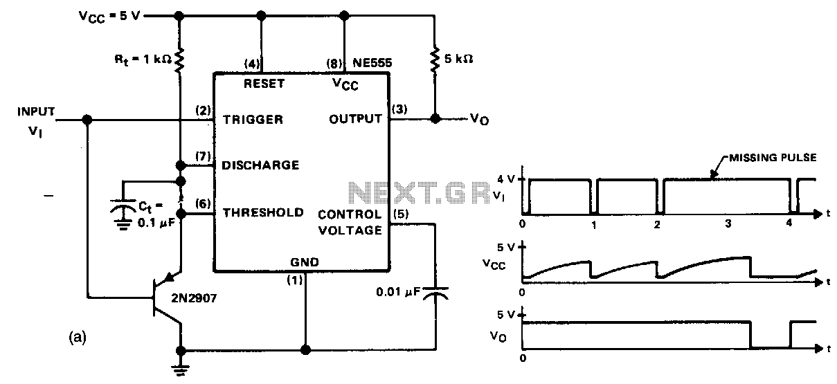
This circuit detects a missing pulse or an abnormally long interval between consecutive pulses in a pulse train. The timer is configured in monostable mode, with the time delay set slightly longer than the duration of the input pulses....
Unique applications of the 567 tone/frequency decoder IC include a pulse generator with a 25% duty cycle (active factor). This signal generator produces a specific output. The 567 tone/frequency decoder IC is a versatile component widely utilized in various electronic...