
Sound-modulated light source
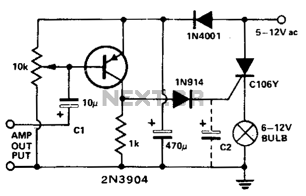
The described circuit utilizes a transistor configured as a peak detector to modulate light intensity based on audio input. The 10 K potentiometer allows for fine-tuning the voltage bias at the base of the transistor, ensuring that it operates within the desired threshold for detecting peaks in the audio signal. When the audio signal exceeds this threshold, the transistor conducts, enabling current to flow through the gate of the SCR.
The SCR acts as a switch that controls the power delivered to the bulb. As the audio signal fluctuates, the SCR turns on and off, leading to variations in the bulb's brightness corresponding to the amplitude of the sound. This modulation creates a visual representation of the audio signal, providing an engaging effect.
In applications where a quicker response is required, the capacitor C2 can be removed. This alteration reduces the circuit's time constant, allowing the SCR to react more swiftly to changes in the audio signal. However, it is essential to consider that eliminating C2 may lead to a less stable operation under certain conditions, potentially resulting in flickering of the bulb.
Overall, this circuit exemplifies a simple yet effective method for visualizing audio signals through light modulation, combining basic electronic components to achieve a dynamic interaction between sound and light.This circuit modulates a light beam with voice or music from the output of an amplifier. If the 10 K pot is adjusted to slightly less than the Vbe of the transistor, the circuit forms a peak detector This drives the gate of the SCR, lighting the bulb whose brightness will vary as the sound level varies. C2 may be removed for a faster response. 🔗 External reference
Related Circuits
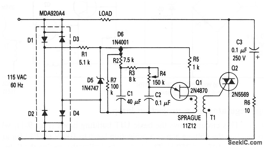
This circuit illustrates the fundamental UJT building block, utilized in a light dimmer with soft-start functionality. It gradually applies current to the light, effectively minimizing high surges (high inrush current) that typically occur in cold-filament light dimmers, which can...
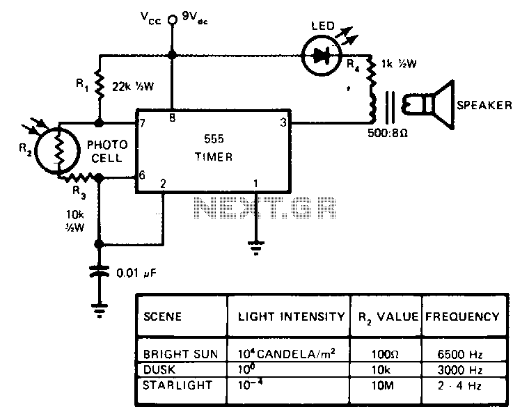
This circuit's frequency of oscillation increases directly with light intensity. The greater the light intensity, the higher the frequency of the oscillator. The 555 timer operates in the astable oscillator mode where frequency and duty cycle are controlled by...
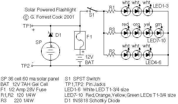
Tired of always spending money on flashlight batteries only to have them fail just when you need them? Try this simple circuit out. It would make an excellent science fair project. The white LEDs are quite bright, they provide...

Cl, VDI, VD2, C2 form a simple capacitive step-down voltage regulator circuit with a rectifier output providing approximately 8V DC voltage for the LM567. A 5.6-foot manifold is connected. Resistors R3, RP, and capacitor C3 create an ultra-low frequency...
This stand-light features a 1000 µF capacitor (C5) that connects the dynamo to the lights. The capacitor cuts off power to the lights at low speeds. While this effect may be negligible for a bottle dynamo, it could be...
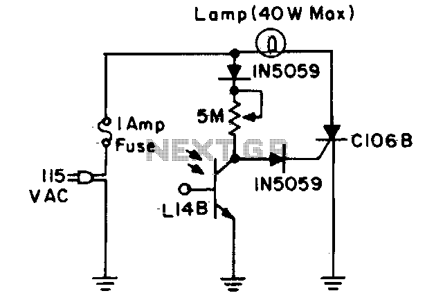
During daylight hours, the L14B photo-Darlington (registered as 2N5777 through 2N5780) shunts all gate current to ground. At night, the L14B effectively provides a high resistance, diverting the current into the gate of the C106B and turning on the...