
Spice and the art of preamplifier design
The phono preamplifier circuit operates by amplifying the low-level signal from the phono cartridge before it is processed by the equalizer. The choice of active feedback versus passive equalization significantly impacts the design and performance of the circuit. The use of a 12AX7 tube is common for its high gain and low noise characteristics, but the limitations of only three sections necessitate careful design considerations to achieve the desired gain levels.
In a typical configuration, the first stage utilizes two sections of the 12AX7 in a mu-follower arrangement, providing the necessary gain while maintaining low output impedance. The feedback network is designed to optimize the frequency response and minimize distortion. The introduction of the Miller capacitor (C1M) is a crucial enhancement, stabilizing the feedback loop and ensuring that the circuit remains free from oscillations, particularly at high frequencies where the loop gain is significantly high.
The adjustments made to the RIAA network play a vital role in ensuring that the frequency response remains accurate across the audio spectrum. By recalibrating the feedback and gain characteristics, the circuit can effectively accommodate variations in tube performance, ensuring consistent sound quality.
The overall design emphasizes reliability and performance, ensuring that the phono preamplifier can handle the nuances of various cartridge types while providing a clean and accurate audio signal. The careful selection of components and circuit topology reflects a commitment to high-fidelity audio reproduction, making this phono preamplifier a robust solution for audiophiles and music enthusiasts alike.One of the principal choices in phono preamplifier design is between active (feedback) and passive equalization. The ideal feedforward preamplifier for a moving magnet cartridge would have about 40dB gain prior to the equalizer (more for low-output moving coil cartridges) and 20dB gain following it This isn`t really practical with the three 12AX7 sections available for the phono preamplifier.
We could use two sections in a mu-follower configuration to get the 40dB gain, but since no extra gain is available for feedback, the gain of this stage is entirely dependent on the amplification factor of the lower 12AX7. This could result in an imbalance between channels if tubes are not absolutely identical. With the help of SPICE, we have been able to design a feedback phono preamplifier with flawless performance (above).
Except for a few small changes, the circuit topology is similar to the `94 mod. We now use dc-coupling in the negative feedback circuit. Since there is little feedback at low frequencies, this makes less difference than it does for the line amplifier, but eliminating an unnecessary capacitor never hurts. We have eliminated the positive feedback resistor (RPFB in Fig. 1) between the gain stage cathodes. We have added resistor RPL at the output to prevent switching pops that can result from charging of output capacitor C5C.
Most importantly, we have added 33 pF capacitor C1M between the grid (node 1G) and plate (node 1P) of input stage TU1. A capacitor connected between a grid and plate is called a Miller capacitor after the Miller effect: Its capacitance must be multiplied by the closed-loop gain of the tube to calculate the correct RC time constant.
This capacitor stabilizes the feedback loop (very important because of the extremely high loop gain at high frequencies), reduces sensitivity to RF interference, and continues the RIAA rolloff at very high frequencies. Its value is not critical: 22 to 47 pF is OK. Before it was added, certain Chinese 12AX7`s (which may have high cathode-to-grid capacitance) appeared to oscillate, as evidenced by a large pop not audible with other tubes when the PAS was switched to PHONO.
Adding C1M eliminated the pop, and the Chinese tubes now sound beautiful. Transient response problems in feedback phono preamplifiers can be completely eliminated by the addition of a Miller capacitor. C1M also gave the PAS a stronger subjective sense of silence in quiet passages: something that can be felt rather than measured.
The RIAA network has been recalculated to improve frequency response accuracy and to increase feedback at low frequencies so that errors due to differences between tubes are minimized. Since the original design has more then enough gain for modern moving magnet cartridges, we are able to increase feedback by reducing circuit gain.
The redesign started by reducing RIA2 from 4. 7MEG to 2. 2MEG. Other component values (RIA2, CIA1, CIA2) were determined by trial-and-error. Frequency response (below) is nearly ruler-flat from 20Hz to 100kHz. Unless you are using the SPECIAL input for a microphone (in which case you`re on your own) I recommend removing the wires that connect terminals 2, 3, 8, and 9 of the phono preamp board to the selector switch and removing the 🔗 External reference
Related Circuits

Transistors are essential components of electronic circuits. The success of a circuit design depends on the selection of the appropriate transistor type and the calculations involved. Transistors serve as fundamental building blocks in electronic circuits, playing critical roles in amplification,...
As shown in the generator start battery automatic monitor circuit diagram. The generator start battery automatic monitor circuit is designed to oversee the battery's status during generator operation. This circuit ensures that the battery remains charged and functional, preventing premature...
The intersection of industry and data collection systems includes hydrometeorological control systems, robot control systems, and digital image transmission systems. This is facilitated by the electron transport of data information. The data transmission system is a crucial component of...
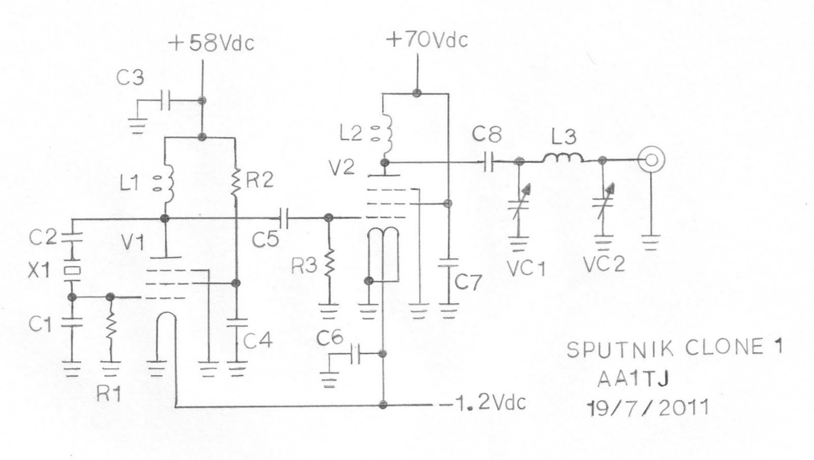
This document describes a prototype transmitter for the Sputnik QSO Party. The RF output power is 450 mW, with 70 V DC at 14.4 mA on the V2 anode. The screen current (G2) for V2 is 1.6 mA, while...
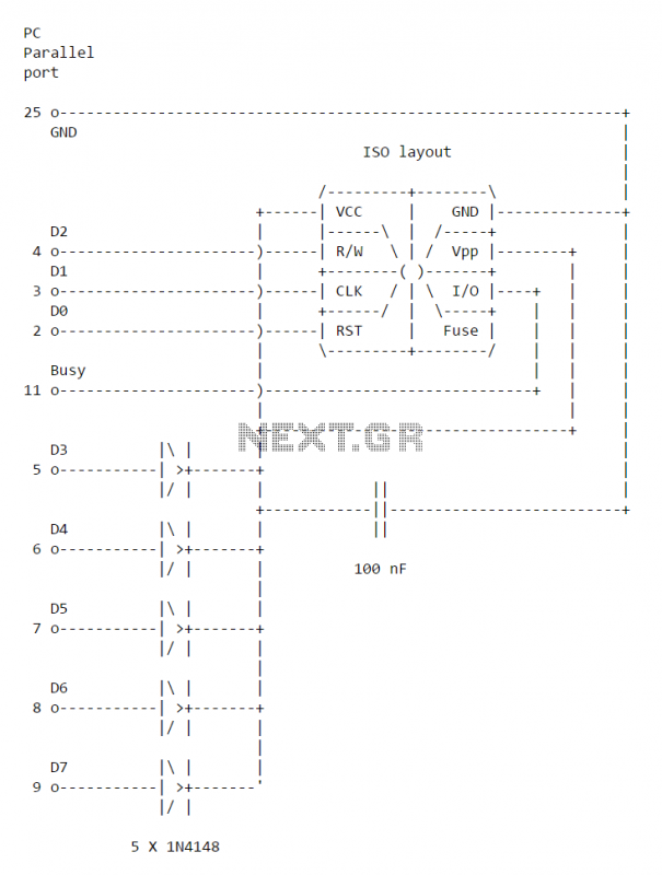
This simple PC Smartcard reader was shown in Electronics Design magazine February 17, 1997 issue on page 172 in the ideas for design section. The circuit is designed by Jose Carlos Cossio and is based on simple smartcard reader...
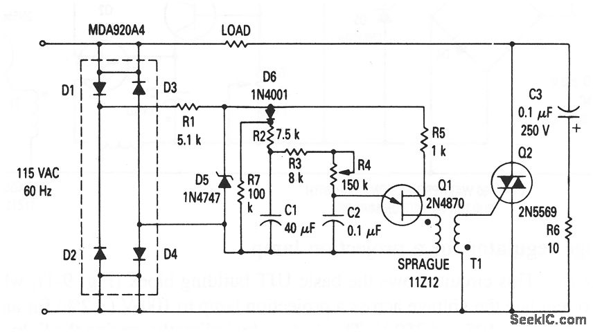
This circuit illustrates the fundamental UJT building block, utilized in a light dimmer with soft-start functionality. It gradually applies current to the light, effectively minimizing high surges (high inrush current) that typically occur in cold-filament light dimmers, which can...