
square wave oscillator circuit
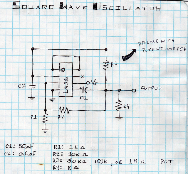
The square wave oscillator circuit is designed to generate a digital square wave signal, which is particularly useful for applications that require simple tone generation, such as synthesizers or sound effects. The core of the circuit is the LM386 amplifier, which is a low-voltage audio power amplifier that can drive small speakers or headphones. The power switch allows for easy operation, ensuring that the device can be turned on and off conveniently.
The potentiometer in the circuit serves as a tone control, enabling the user to adjust the frequency response of the oscillator. This feature is essential for tailoring the sound output to the desired tonal quality. The normally closed momentary switch adds an interactive element, allowing the user to momentarily stop the sound when pressed, which can be useful for creating rhythmic patterns or sound effects.
In the schematic, the connections are clearly marked, with non-connections indicated by red X's to avoid confusion during assembly. The black dots signify where wires should be connected, ensuring that the circuit functions as intended. The additional square wave oscillator described in the second video expands on the original design by incorporating keys that allow for switching between different tones, enhancing the versatility of the device. Each key, when pressed, activates a resistor that generates a distinct tone, demonstrating a practical application of momentary switches in sound synthesis.
Overall, this circuit design represents a straightforward yet effective approach to generating square wave signals, suitable for various electronic music applications or sound experimentation.This is a square wave oscillator (digital, like 8-bit music). It`s based around the LM386 amplifier I. C. , which is what the mini guitar amplifier was based on. It has a simple power switch connected to the battery, a potentiometer for adjusting the tone, and a normally closed momentary switch. The momentary switch is connected to the signal output . It`s normally closed so when you press it, the signal is cut off but when you release it, the signal passes through again to your amplifier. This can create some cool sounds. This is a diagram showing the components wired to the I. C. The red x`s indicate places where the wires don`t connect and the black dots indicate connections. Feel free to download the image here. This second video contains another square wave oscillator but with keys to jump to different tones and a potentiometer to adjust the overall tone.
The keys are actually normally closed momentary switches. A resistor is connected to each switch so when it is pressed, it generates a tone. It`s hard to explain here so I`ll try to explain it later or in a video. 🔗 External reference
Related Circuits
A crystal oscillator operates at a frequency of 51 MHz, which corresponds to the third harmonic of a 17 MHz fundamental frequency. Depending on the specific structure used, the drain-gate capacitance can be selected within a range of 0.5...

This circuit is beneficial for amateur radio operations in VHF and UHF frequencies, where a mast-mounted antenna preamplifier is employed for reception. The kit manages the transmit-receive (T-R) switching and relay sequencing to prevent high RF levels from being...
Design a circuit using a power MOSFET to replace the NTC thermistor that many Mag623 users employ to prevent their bulbs from flashing. Although inexpensive and easy to connect, NTCs run quite hot, are affected by ambient temperature, require...
All sound effects are generated internally by the HT2884 integrated circuit (IC). The device operates on a 3-volt battery but is compatible with any voltage ranging from 2.5 to 5 volts. Switch S1 functions as the on/off switch. The...
The Hartley Oscillator is characterized by an LC circuit in its collector. The base of the transistor is held steady, and a small amount of signal is taken from a tapping on the inductor and fed to the emitter...
This circuit utilizes a JFET to receive signals from an LED and buffer them. The output voltage is managed using an IC 1458 or LM1458, which provides approximately 7 volts in darkness and experiences a drop of about 2...