
Preamp Transmit-Receive Sequencer Circuit
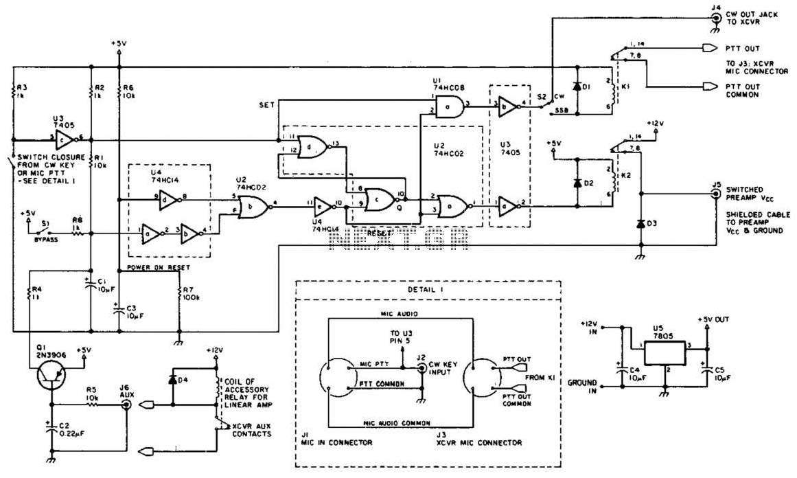
The circuit utilizes a relay-based system to facilitate the switching between transmission and reception modes, ensuring that the preamplifier is protected from potentially damaging RF signals during the transition. The design typically includes a control circuit that triggers the relay based on the operational state of the radio equipment.
In the reception mode, the mast-mounted antenna preamplifier amplifies weak signals received from the antenna, enhancing the overall performance of the radio system. The preamplifier is strategically placed close to the antenna to minimize signal loss due to cable length.
During the transmission phase, the circuit engages a relay that disconnects the preamplifier from the antenna, effectively isolating it from the high power levels generated by the transmitter. This isolation is crucial to prevent damage to the preamplifier and ensure optimal functionality of the radio system.
Additional features may include LED indicators to signal the current operational mode, as well as additional filtering components to reduce noise and improve signal clarity. The overall design emphasizes reliability and efficiency, making it suitable for amateur radio enthusiasts who require robust performance in their VHF and UHF communications. Proper attention to component ratings and circuit layout is essential to maintain signal integrity and protect sensitive components from high RF levels. This circuit is useful in amateur radio VHF and UHF work where a mast-mounted antenna preamp is used for receiving. The kit controls T-R switching and change-over relay sequencing so that high RF levels are prevented
from accidentally being applied to the preamplifier during switching intervals. 🔗 External reference
Related Circuits
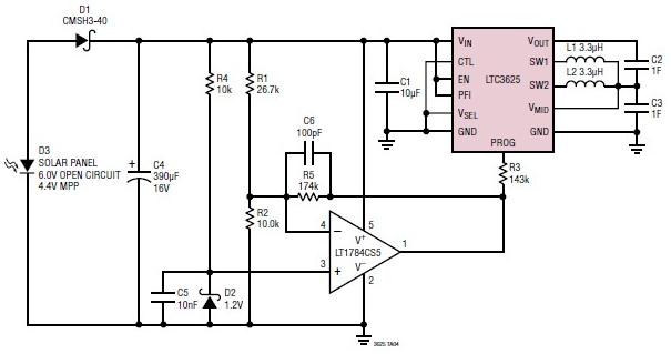
A simple supercapacitor charger electronic project can be designed using the LTC3625 integrated circuit (IC) from Linear Technology. This circuit is capable of charging two supercapacitors in series to a fixed output voltage of either 4.8V/5.3V or 4V/4.5V, which...
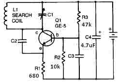
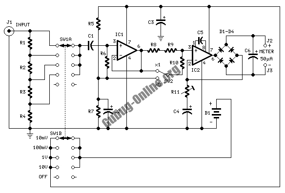
This metal detector circuit needs to be powered using a 9 volts power supply (DC) or a 9 volts battery. The C1 capacitor is a variable capacitor with a value of 365 pF, C2 is a 100 pF silver...
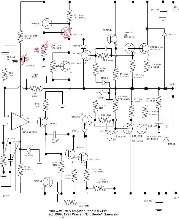
This is a 100-watt basic power amplifier designed to be relatively easy to build at a reasonable cost. It offers better performance, or musical quality, than the standard STK module amplifiers commonly found in mass-market stereo receivers. The design...
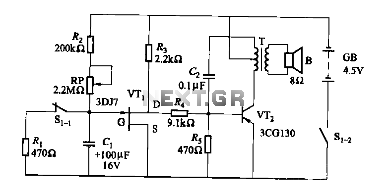
The darkroom circuit is designed for one-time exposure and emits an audible signal when the developing time is reached. This circuit can be utilized for photofinishing large timers and other applications. It comprises components such as FET VTi, resistors,...
This is a circuit design for a temperature relay that can be used to signal a fire or monitor temperature set points. The adjustment of P1 is necessary to ensure that the base voltage of T1 is 0.5V lower...
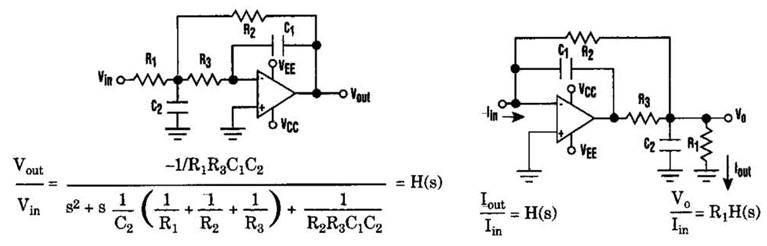
Current-Driven Sallen-Key Filter Circuit Diagram. The low-pass Sallen-Key filter is a staple for designers because it contains few components (A). The Sallen-Key filter is a widely used active filter topology that employs operational amplifiers (op-amps) to achieve desired filtering...