
Stepper Motor Project

The microcontroller board serves as the central control unit for the entire system, coordinating the operation of the stepper motors and interfacing with external components such as the IR sensor and remote control. The programming jumper is a critical component that allows the unit to switch between program mode and operational mode, enabling flexibility in control methods. The inclusion of the IR sensor enhances user interaction by allowing remote control functionality, which is particularly useful for applications requiring precise motor movements.
The stepper motors utilized in this design are geared Hurst stepper motors, which provide accurate positioning and control over movement, making them suitable for applications where precise angular displacement is required. The connection of the motors to the six-pin headers ensures a reliable interface for power and control signals.
The activation switch plays a pivotal role in the system, providing a manual method to control the bridge's position, while the sound unit or other accessories can be integrated through the screw terminals, allowing for further expansion of system capabilities.
In operational mode, the toggle switch allows for straightforward activation of the motors via a push button, simplifying user interaction. The system's design also incorporates safety features, such as the ability to retain the last known position of the bridge in case of power loss, which minimizes potential damage or operational issues.
Overall, this microcontroller-based system is designed for versatility and ease of use, making it suitable for various applications requiring controlled movement and remote operation.The microcontroller board is shown (top left/green board) along with the auxiliary board (bottom left / brown board) and the two geared Hurst stepper motors. In this view of the microcontroller board the programming jumper is in the upper right area. Power is applied in the lower right. The IR sensor is in the upper left next to the yellow LED. The stepper motors connect to the two six pin headers on the left side of the second board, seen below. The activation switch (which moves the bridge up or down) connects at the bottom center and the sound unit or other accessory connect via the screw terminals on the bottom left.
When the programming jumper is in place the unit is in program mode and functions can be controlled by the TV remote control unit. The unit used in this example is a Philips CL015 that is programmed to emulate a Sony remote 1. Make sure the programming jumper is on the two jumper pins on the green microcontroller board. This allows the remote control unit to operate the motors 2. Type a 4 digit number of degrees, for example 0720 for 2 rotations (720 degrees) - note that the LED flashes out each digit as it is entered - please allow time for each digit to flash out before entering the next digit.
Pressing the UP/DOWN button will move the motors the programmed number of degrees. The first press of UP/DOWN moves the motors CW. The second press moves the CCW. Note. If power is lost while the bridge is up the unit will remember that is was up and the next press will put the bridge down. If power is lost in the middle of an up or down operation the bridge controller will not know where the bridge was stopped and the unit must be reset by with the remote control unit - (install the programming jumper and use the 1-6 keys (as above) to move the bridge to the bottom or top position before restarting.
Connect the unit as below for testing. The grey wires on the left go to the Program / Operate toggle switch. In the program position the remote control can change setting and align the motors. In the Operate setting the push button (at the end of the blue/white wires) activates the motors either up or down. Note that the blue / white wires terminate in a small plug that goes into the board next to the black screw terminal connector.
The red/white wires in the lower left terminate in a power connector that goes to the power supply. The two pairs of black / white wires are for the NO contacts on the relay. They connect via the two sets of screw terminals marked NO. 🔗 External reference
Related Circuits
This is a Class D audio amplifier circuit used to control the PWM motor speed. This circuit has two advantages for battery-powered portable devices. First, it provides high efficiency, which extends battery life. The Class D audio amplifier operates by...
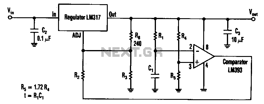
The timed two-voltage circuit can start and run a small DC motor or solenoid. The input voltage to the LM317 three-terminal regulator ranges from 5 to 40 V, and the output voltage can range from 2 to 36 V....
The P5 design utilizes eight 74HC/AC240 chips, which function as octal inverting buffers. Each 74HC/AC240 chip contains two groups of four inverters, each managed by a tri-state enable pin (pins 1 and 19). The 74AC240 chips (U1-U5) serve as...
Schematic of Big Trak's motor driver circuit. The toy includes 9112 and 9113 transistors (and sometimes 2N6715) because the 75494 chip cannot supply enough current to run the Big Trak's motors by itself. The motor driver circuit for the Big...
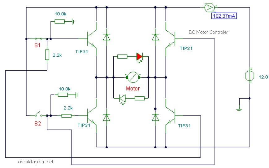
This is a DC motor controller circuit built using the TIP31 transistor based on the H-Bridge concept. The switches S1 and S2 are normally open, push-to-close buttons. The LED serves to indicate the direction of motor rotation and any...
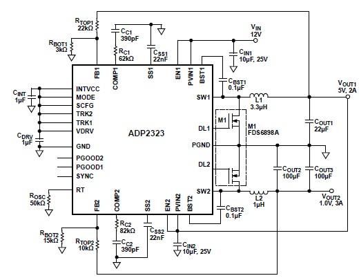
The ADP2323 DC-DC converter is designed to deliver two output voltages with specified maximum output currents. The first channel provides a 5-volt output with a maximum current of 2 Amperes, while the second channel supplies 1 volt with a...