
dc motor controller circuit
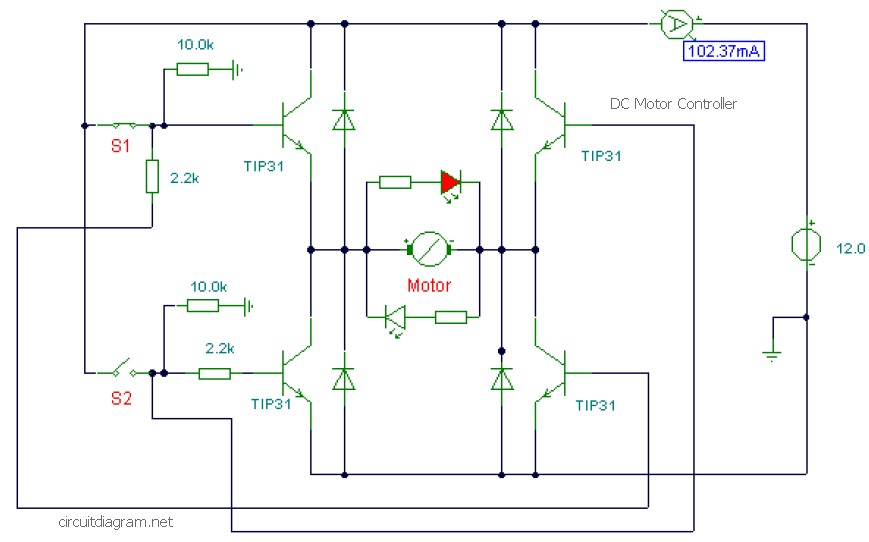
This DC motor controller circuit is designed to effectively manage the speed and direction of a DC motor using an H-Bridge configuration. The TIP31 transistors are utilized for their ability to handle currents up to 3A, making them suitable for various motor applications. The circuit's push-button switches (S1 and S2) allow for simple user interaction to change the motor's direction. The LED indicator provides visual feedback on the motor's operational state, enhancing user experience and safety.
The integration of the Maxim MAX4295 in this design facilitates precise control over the motor speed. The resistor R1 plays a critical role in ensuring that the potentiometer's output is compatible with the input requirements of the MAX4295, allowing for smooth transitions in motor speed. The PWM control implemented through the NE556 timer IC is essential for efficient motor operation, as it modulates the power supplied to the motor, thus controlling its speed effectively.
The additional features of this circuit include an automatic water pump controller, which is particularly useful in applications where water levels need to be managed without manual intervention. This system automatically activates the pump when the water level drops, ensuring that the overhead tank is refilled as necessary.
Moreover, the automatic light controller component employs the 78xx series voltage regulators to maintain a stable output voltage, which is crucial for consistent operation of the connected devices in varying input conditions. The electronic motor starter circuit adds further protection for single-phase motors, ensuring longevity and reliability by preventing damage from voltage spikes and overloads. The transformer and rectification components work together to provide a safe and controlled power supply to the motor, enhancing the overall functionality of the system.This is a DC motor controller circuit, built using transistor TIP31 based on H-Bridge concept. The switch S1 and S2 are normally open, push to close, press button switches. The LED function is to indicate the direction of motor rotation, you may use any common LED type. The TIP31 transistors capable to handle 3A. This is a motor speed controller circuit diagram built based Maxim MAX4295. This with this circuit you will be able to control the speed of motor rotation. Resistor R1 biases the potentiometer to match the input range of U1. Full counter-clockwise rotation of the pot corresponds to maximum-speed reverse rotation of the motor. Mid-scale on. This is the schematic diagram of DC motor speed controller circuit. The circuit applies two oscillators/timers which are connected as a Pulse Width Modulator (PWM). The timer chip which applied in this circuit will be an nmos dual timer/oscillator NE556. This timer IC has two 555 timers in a single 14-pin IC package. One 555. Here the circuit diagram of low cost water pump controller. The automatic pump controller minimizes the need for any manual switching of water pumps installed for the functionality of pumping water from a reservoir to an overhead tank.
It instantly switches on the pump once the water level within the tank falls below a. This is the circuit diagram of automatic light controller which use 78xx voltage regulator IC series. The voltage regulator ICs deliver a constant output voltage, as against a extensively fluctuating input supply, when the common terminal is grounded.
Any voltage about zero volt (ground) interconnected within the common terminal is added to the output voltage. . The above diagram is the schematic diagram of an electronic motor starter circuit. This motor starter protects singlephase motors against voltage fluctuations and overloading. Its salient function is a soft on/off electronic switch for simple operation. The transformer steps down the AC voltage from 230V to 15V. Diodes D1 and D2 rectify the AC voltage. 🔗 External reference
Related Circuits
The circuit is designed to deliver a surge current of 12 amps, offering performance that meets or surpasses that of typical commercial units. Additionally, it incorporates a current limiting feature, providing a level of reliability that is superior to...
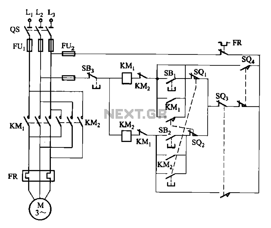
The circuit illustrated in Figure 3-132 represents an automatic round-trip plug braking circuit. To prevent or limit malfunctions of switch SQ1 and switch SQ2 that could lead to accidents, two additional protection limit switches, S03 and S04, have been...
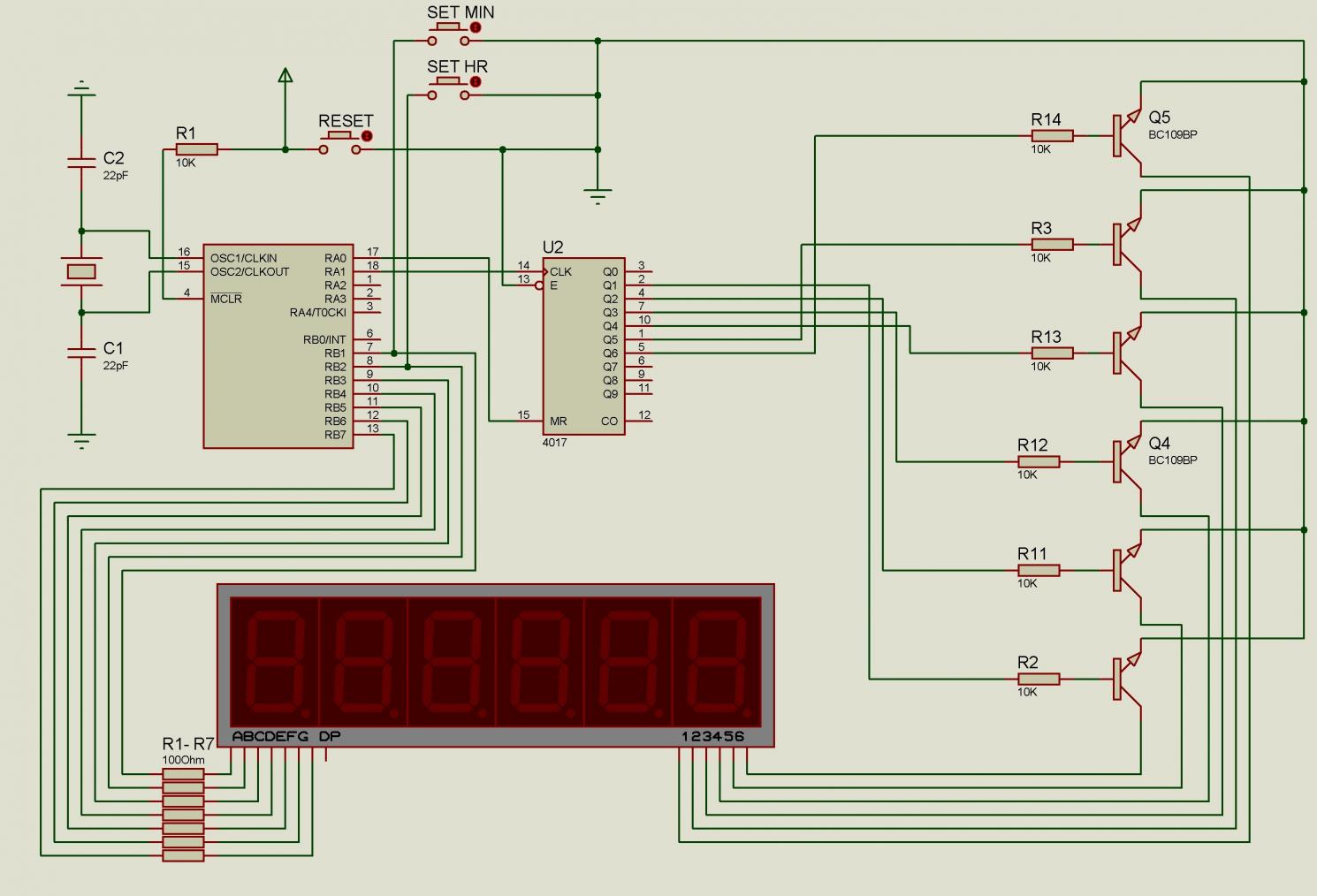
There are issues with simulating this circuit on Proteus. Please review it to ensure no errors were made. The user is also a novice. The circuit simulation in Proteus can often present challenges, especially for those who are new to...
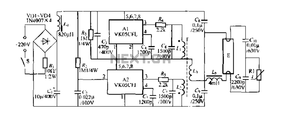
Figure 289 illustrates the VK05CIl, an ASIC produced by STMicroelectronics (ST) designed to operate low-power compact fluorescent lamps ranging from 5 to 15W. The VK05CFI is engineered to drive approximately 23W low-power compact fluorescent lamps using high-pressure composite bipolar...
The need for a device that can detect and extinguish a fire on its own is long past due. Many house fires originate when someone is either sleeping or not home. With the invention of such a device, people...
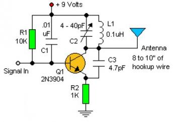
Experimenting with the size of the coil and the number of turns can influence the frequency and signal output of the oscillator. The signal can be received using a standard FM radio receiver. The input signal should be coupled...
Warning: include(partials/cookie-banner.php): Failed to open stream: Permission denied in /var/www/html/nextgr/view-circuit.php on line 713
Warning: include(): Failed opening 'partials/cookie-banner.php' for inclusion (include_path='.:/usr/share/php') in /var/www/html/nextgr/view-circuit.php on line 713