
Stepping Motor Driver
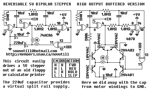
This circuit is designed for controlling a stepper motor with features that allow for precise movement in both forward and reverse directions, as well as maintaining its position when powered. The operation modes include FULL STEPS FORWARD and FULL STEPS REVERSE, which enable the motor to move incrementally by energizing the motor coils in a specific sequence.
The ACTIVE HOLD feature is essential for applications where the motor must maintain its position without moving, ensuring that the motor does not lose its holding torque when not actively stepping. The POWER OFF or RELEASED mode allows for the motor to be powered down completely, which can be useful for reducing energy consumption when the motor is not in use.
In the event that the motor does not turn, a troubleshooting step involves swapping the leads of one of the two coils. This adjustment can correct the phase of the motor coils, which is crucial for proper operation. The circuit incorporates an EN (enable) signal that controls the activation of the motor. To modify the behavior of the EN signal, the circuit can be reconfigured using an XNOR gate. This logic gate will allow for the reversal of the EN signal sense, enabling flexibility in the control logic depending on the system requirements.
Overall, the circuit is robust against motor transients, which are sudden changes in voltage or current that can occur during motor operation, ensuring reliable performance in various applications. The design considerations make it suitable for environments where precise motor control is necessary.The circuit is not particularly susceptible to motor transients and supports FULL STEPS FORWARD, FULL STEPS REVERSE, ACTIVE HOLD, and POWER OFF aka RELEASED. If the motor does not turn then swap around the leads of ONE of the two coils. To reverse the sense of the EN signal simply rework the circuit around an XNOR gate. 🔗 External reference
Related Circuits
All errors in circuit diagrams, documents, and layout have been corrected. The circuit shown is functional and operational. It is important to note that Q2 is sensitive and can be easily damaged by incorrect connections, shorts, over-voltage, or excessive...
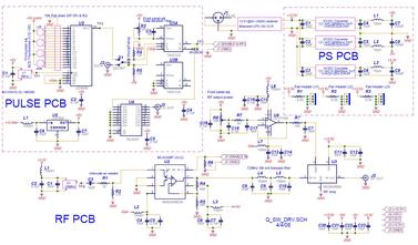
The Q-Switch driver for an old YAG laser failed. A replacement was over $1000, so a custom driver was built for less than $300 (see picture and schematic below). The specifications required were at least 20W into a 50-ohm...
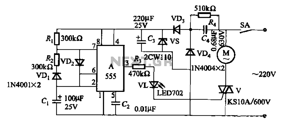
The circuit depicted in Figure 3-16 utilizes a 555 IC (Integrated Circuit) as the control element. It features a capacitive step-down circuit and incorporates a bidirectional thyristor (V) for intermittent motor control operation. By adjusting the resistance values of...
This is a status panel driver circuit. This circuit is used to turn on lamps or LEDs in a graphic panel that represent faults, actions, and the status of an application. The status panel driver circuit is designed to control...
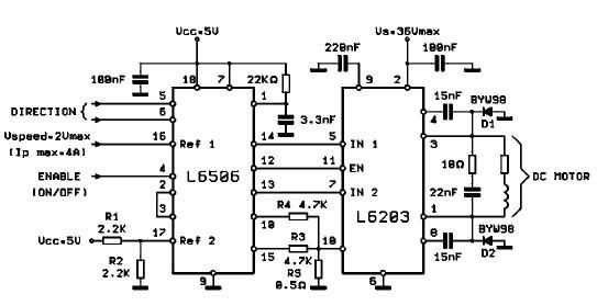
The L620x is a monolithic full bridge switching motor driver implemented using the new Multipower-BCD technology. This technology enables the integration of multiple isolated DMOS power transistors along with mixed CMOS/bipolar control circuits. The L620x series includes various versions:...
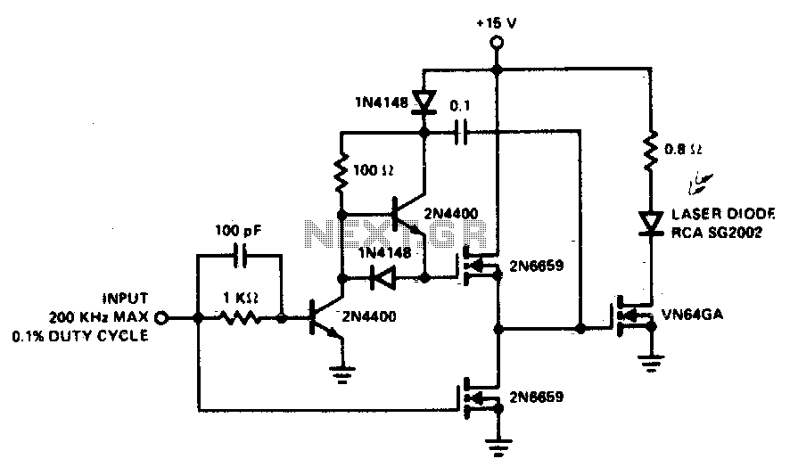
A faster driver can supply higher peak gate current to switch the VN64GA very quickly. The circuit uses a VMOS totem pole stage to drive the high power switch. The described circuit employs a high-speed driver to enhance the switching...
Warning: include(partials/cookie-banner.php): Failed to open stream: Permission denied in /var/www/html/nextgr/view-circuit.php on line 713
Warning: include(): Failed opening 'partials/cookie-banner.php' for inclusion (include_path='.:/usr/share/php') in /var/www/html/nextgr/view-circuit.php on line 713