
Single-phase motor automatic intermittent operation control circuit
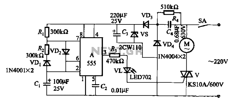
The circuit operates using the 555 timer in an astable mode, providing a square wave output that controls the bidirectional thyristor. The thyristor acts as a switch that allows current to flow to the motor during the 'on' phase of the 555 timer output. The use of a capacitive step-down circuit ensures that the voltage supplied to the motor is reduced, protecting it from overvoltage conditions and allowing for controlled operation.
The timing of the motor's operation is determined by the values of the resistors Ri and R2, as well as the capacitor C1. The relationship between these components can be described by the timing equation for the 555 timer, which dictates the duration of the high and low states in the output signal. By modifying these values, the user can achieve the desired operational characteristics of the motor, such as varying the running time or the downtime.
In practical applications, this circuit can be employed in various motor control scenarios, such as in automated systems where motors need to operate intermittently. The precise control over the motor's running and stopping times allows for efficient energy use and can enhance the overall performance of the system. The bidirectional thyristor adds versatility, enabling the circuit to control motors that may require reverse operation, depending on the application needs. Circuit shown in Figure 3-16. It uses 555 IC A as the control element; capacitive step-down circuit; bidirectional thyristor V between the motor control intermittent operation. Adjusting the resistance Ri, R2 or capacitance value Cl allows you to change the motor running and stop time. Press the icon parameters, the running time is 50s, downtime 15s.
Related Circuits
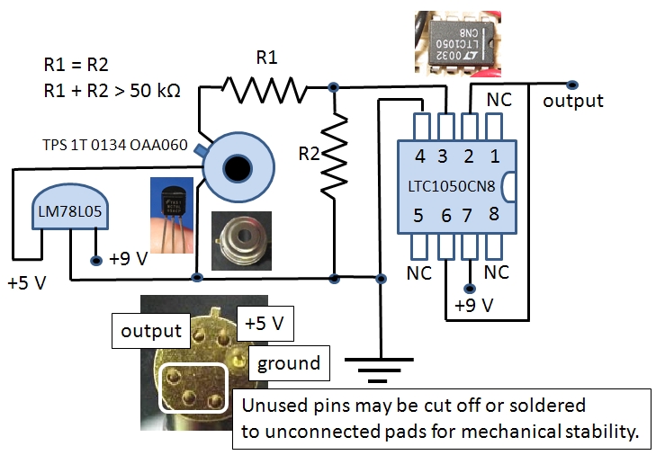
The Excelitas TPS 1T 0134 OAA060 thermopile sensor is a self-contained module that includes a built-in operational amplifier. The designation A2TPMI 334 OAA 60 is used in this document due to its previous identification under the PerkinElmer part number...
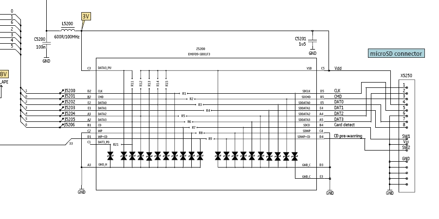
In this tutorial, the functioning of the memory card circuit in mobile phones will be explored. The previous post discussed the pin-outs and types of memory cards utilized in cellular devices. The accompanying block diagram illustrates how the removable...
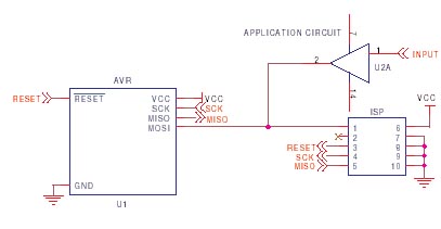
It is crucial to design the PCB layout correctly to enable seamless In-System Programming (ISP) of AVR microcontrollers. This guide addresses common issues encountered and provides typical AVR ISP circuit schematics. It focuses on Serial Programming, known as ISP,...
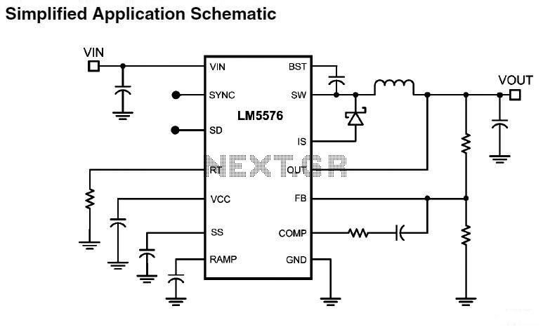
LM5576MHX absolute maximum ratings: (1) VIN to GND: 76V; (2) BST to GND: 90V; (3) PRE to GND: 76V; (4) SW to GND (Steady State): -1.5V; (5) BST to VCC: 76V; (6) SD, VCC to GND: 14V; (7) BST...
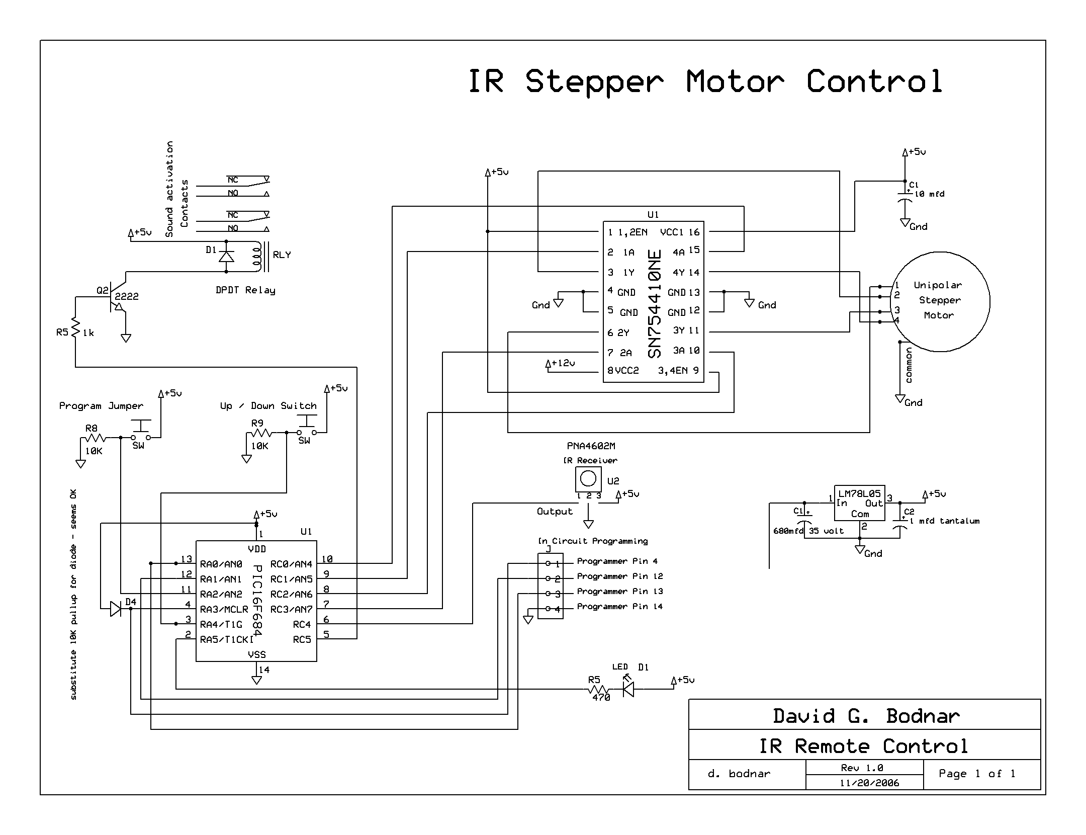
The microcontroller board is displayed (top left/green board) alongside the auxiliary board (bottom left/brown board) and two geared Hurst stepper motors. In this view, the programming jumper is located in the upper right area of the microcontroller board, while...
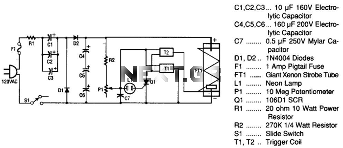
This strobe light operates from standard 120-Vac power. Resistor R1 limits the amount of current applied to the voltage doubler stage, which consists of capacitors C1, C2, C3, and diodes D1, D2, along with capacitors C4, C5, and C6....
Warning: include(partials/cookie-banner.php): Failed to open stream: Permission denied in /var/www/html/nextgr/view-circuit.php on line 713
Warning: include(): Failed opening 'partials/cookie-banner.php' for inclusion (include_path='.:/usr/share/php') in /var/www/html/nextgr/view-circuit.php on line 713