
stereo led power vu meter
It is supplied from the 12 V car electrical system and is suitable for classical CC (Capacitor-coupled) as well as BTL (Bridge Tied Load) types of amplifier with no changes to the circuitry or connections at all. In fact, only the meaning of the LEDs changes ” with BTL, the LED increments equal four times the CC value on the same load.
CC-type amplifiers have the loudspeaker connected via a DC-decoupling capacitor at the output and ground (negative). BTL-type amplifiers, on the other hand, have the loudspeaker DC-coupled and stretched` between two equal, parallel, but phase-reversed outputs.
The result compared to CC` is twice the voltage swing, hence quadrupling the power being fed to the same loudspeaker load. It is necessary to know to which of the two types this circuit is connected to only in order to correctly assign power levels (W) to the LEDs.
CC-type have no DC voltage to ground at the outputs and return wires. The return wires are actually connected to the common ground (negative). BTL-type have approximately Vcc/2 at outputs and on the return wires too, explaining at the same time why no DC-decoupling capacitors are needed. The LM3915N integrated circuit used in this circuit has been the subject of numerous publications in this magazine so will not will not be discussed again.
In this application, the two LM3915Ns are configured as a LED bar graph drivers (pin 9 connected to pin 3), The ICs share the same power supply section. The audio input signal is fed via network C1/C2, R1, R2 (C3/C4, R5, R6) to pin 5 of IC1 (IC2). Only positive half-waves are processed by the ICs. Internally, the buffered input voltage is compared using comparators to the voltages along a resistor ladder network.
The nominal +1. 25 V reference source voltage (between pins 7 and 8) is applied across R3 (R7) to program the LED current. The programming current flows through R4 (R8) to achieve the desired reference voltage between pin 7 and ground.
Here, only 2. 0 V is developed, allowing this circuit to be used with low power amplifiers too. This voltage is applied to the top` of the on-chip resistor array (pin 6) and so determines the threshold at which the LED connected to the L10 output comes on. The other (low) side of the array (pin 4) is connected to ground. So, for an input voltage equal to or greater than the voltage at pin 6, all LEDs are on. At input voltages below the threshold set up for the lowest LED (89. 3 mV or 27dB below the top LED) all LEDs are off. In order to limit power dissipation of IC1 and IC2, the LED voltage is stepped down to +5 V using IC3, C6 and C7.
Diode D1 protects the circuit against reversed polarity. If a dot` mode graph is preferred pins 9 of IC1 and IC2 should be left open circuit. Using the listed value for R1 (R5), the indicator range covers audio power levels of 10 W into 4 (CC) or 40 W into 4 (BTL). Each lower LED indicates half the power of the previous higher` LED Only R1 (R5) needs to be redimensioned for different power levels.
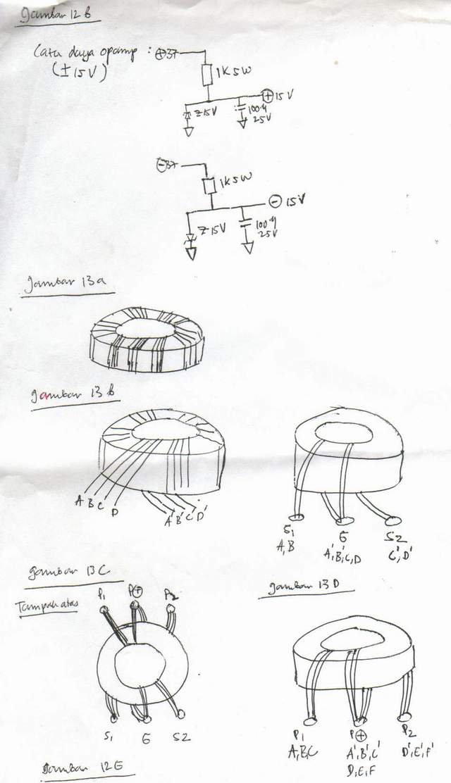
The value can be calculated from R1 = [R2 (PO ZL) / (k * VRefOut)] R2 where PO = maximum output power to be indicated (LED D2 or D12) ZL = loudspeaker impedance R2= R6 VRefOut = 2. 0 V k = constant; 2 for BTL, 1 for CC The condition (PO ZL ) / (kVRefOut) ‰¥ 1 must be met. A small printed circuit board has been designed to allow a stereo version of the power indicator to be built.
The board is cut in two to separate the channels. The boards may be assembled in a sandwich construction with three inter-board connections A-A`, B-B` and C-C` made in stiff wire. IC3 should be secured to a small heatsink (10 K/W). Rectangular-face 🔗 External reference
Related Circuits
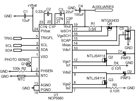
This white LED driver circuit project utilizes the NCP5680 high-efficiency white LED driver integrated circuit (IC). The NCP5680 supports dual power flash LED and torch operations. Its built-in DC/DC converter employs a highly efficient charge pump structure with operating...
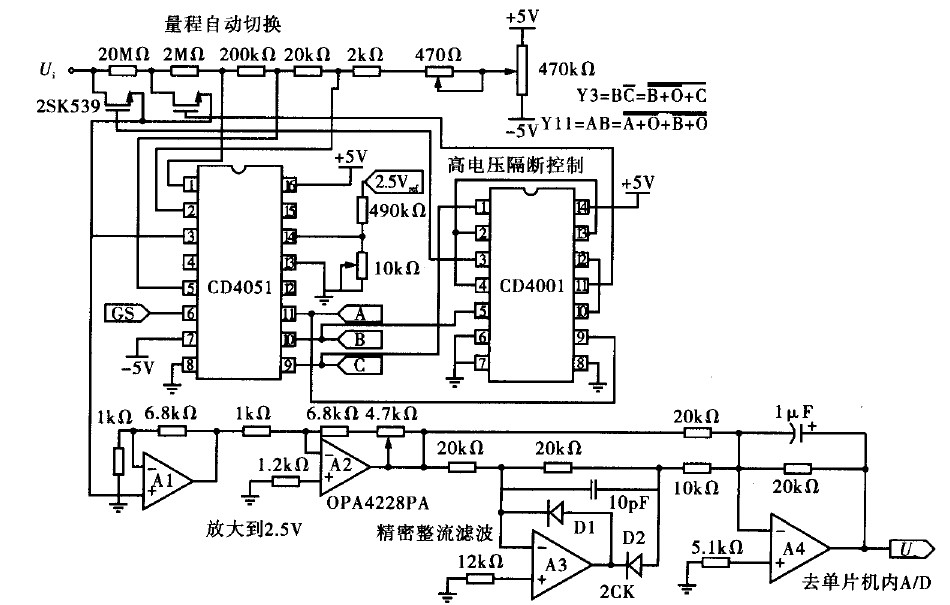
Voltage measurement is a fundamental aspect of electronic technology today, with increasing demands for accuracy and functionality in instruments. This is particularly critical when measuring signals with significant phase differences, as it is essential to ensure the accuracy of...
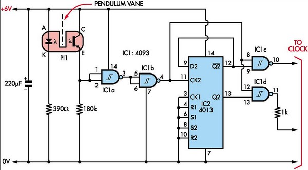
This document outlines the construction of a pendulum-controlled clock designed for high accuracy. Although it has a retro appeal, it represents an intriguing project. The project requires a spare quartz clock, which must be modified by isolating two pads...
This article is intended for individuals interested in constructing their own car amplifier. The fundamental calculations involved will be discussed below. Understanding these concepts will enable the construction of a car amplifier independently. The complexity of designing a car...
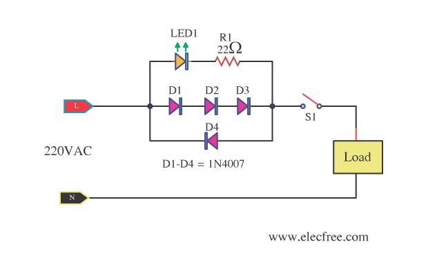
A need exists for a 220V AC line light display or main voltage monitor due to frequent electrical issues in a home. To create a 220V AC line light display or voltage monitor, a circuit can be designed using a...
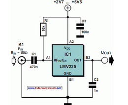
The National Semiconductor LMV225 is a linear RF power meter integrated circuit (IC) in a surface-mount device (SMD) package. It operates over a frequency range of 450 MHz to 2000 MHz. The LMV225 is designed for precise measurement of radio...