
pendulum controlled clock
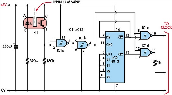
At the lower end of the pendulum, an inverted T-shaped aluminum vane, approximately 10mm wide and as thin as possible, should be attached and painted black. This vane is utilized to activate a photo-interrupter mounted on the backboard. The lengths of the T's arms are designed so that when the pendulum swings in one direction, the interrupter is triggered, allowing light to pass through. Conversely, when the pendulum swings in the opposite direction, the vane continues to block the light. This design enables the pendulum, swinging in 0.5-second beats, to generate a short pulse from the photo-interrupter at one-second intervals. This pulse is then inverted by IC1a and subsequently inverted again by IC1b, which clocks IC2, a 4013 flip-flop. IC2 alternately produces one-second-long pulses at its pin 12 and pin 13 outputs. These outputs are fed into IC1c and IC1d, where they are gated by the short pulses on pin 4 of IC1b, resulting in two short pulses that drive the clock in alternating directions at one-second intervals. This setup is sufficient to operate the clock. Alternatively, this circuit can function as a master clock to synchronize multiple slave clocks, ensuring they remain in time. Model train enthusiasts may also modify the vane by drilling holes to adjust the speed of their "railway" clocks as needed. The circuit can be constructed on a small piece of strip board. It is important to mount the photo-interrupter with the photocell facing the backboard to reduce interference from ambient light. The photo-interrupter is available from Jaycar under catalog number ZD 1901. A note for horologists: if a clock features a Hipp butterfly escapement, the trailing arm and contact arrangement can be replaced with a vane and photo-interrupter setup. This would allow for the detection of missed pulses as the swing arc diminishes, which can trigger a 555 missing pulse detector circuit to energize the impulsing magnet.
The schematic consists of several key components: the pendulum mechanism, the photo-interrupter, and the integrated circuits (ICs) that manage the timing and output signals. The pendulum acts as the primary timekeeping element, with its swing period precisely adjusted to achieve the desired timing accuracy. The photo-interrupter serves as a sensor that detects the pendulum's movement, converting mechanical motion into electrical signals. The ICs, including the 4013 flip-flop, are responsible for processing these signals and generating the appropriate output pulses to drive the clock mechanism.
The overall design emphasizes simplicity and reliability, making it accessible for hobbyists and electronics enthusiasts. Careful attention to the placement of components, particularly the photo-interrupter, is crucial to ensure optimal performance and minimize errors caused by external light sources. This project not only showcases the principles of pendulum mechanics and electronic timing but also provides an engaging opportunity for experimentation and innovation in clock design.Here`s how to build a pendulum-controlled clock which can be made really accurate. Retro - yes, but an interesting project all the same. You`ll need a spare quartz clock which must be adapted by first isolating the two pads on the chip which lead to the coil. You then have to connect wires to these pads and feed them out through a hole in the cas e (see SILICON CHIP, December 1996, p38, for full instructions, or October 2001, p37, for brief notes. ) You`ll also need a spare battery driven pendulum from another, or the same, clock. As originally used, these pendulums are for appearance only and play no role in timekeeping. The salvaged unit should be mounted on a substantial vertical backboard. You`ll find that the pendulum swings pretty fast and it must be slowed down by adding weights near the lower end.
However, it`s not the mass of a pendulum that controls its rate - instead, it`s the distance from the support to the centre of mass that counts. The aim is to make the pendulum operate so that it takes exactly 1s for a full "to and fro" swing - ie, 0.
5s "beats". Fine adjustment on mine was made by adding an adjustable (up and down) weight to the pendulum rod. This consisted of a small G-clamp fabricated from a brass strip and held by a small screw. At the bottom end of the pendulum attach an inverted T-shape aluminium vane, about 10mm wide and as thin as possible. This should be painted black. This vane is used to trigger a photo-interrupter which is attached to the backboard. The lengths of the arms of the "T" are made so that when the pendulum swings one way, the interrupter triggers - ie, the light is no longer blocked.
Conversely, when the pendulum swings the other way, the vane must continue to interrupt the light. This means that, with the pendulum swinging in 0. 5s beats, we get a short pulse from the photo-interrupter at 1s intervals. This pulse is inverted by IC1a and inverted again by IC1b which then clocks IC2, a 4013 flipflop. IC2 alternately produces 1s-long pulses at its pin 12 & 13 outputs. These outputs are then fed to IC1c & IC1d respectively, where they are gated by the short pulses on pin 4 of IC1b. This produces two short pulses to drive the clock in alternate directions at 1s intervals. And that`s all you need to drive the clock. Alternatively, this circuit could be a master clock and could be used to drive several slaves, all remaining in time.
And model train enthusiasts could drill one or more holes in the vane to make their "railway" clocks run at what ever speed they need. The circuit can be built on a small piece of strip board. Note that the photo-interrupter should be mounted with the photocell facing the backboard. This minimizes the risk of interference by ambient light. The photo-interrupter is available from Jaycar - Cat. ZD 1901. A footnote for horologists - if you have a clock with a Hipp butterfly escapement, you could rid yourself of the trailing arm and contact arrangement and replace it with a vane and photo-interrupter set so that as the arc of the swing becomes too small, a pulse is missed.
This could then be detected by a 555 missing pulse detector circuit which would then energize the impulsing magnet. 🔗 External reference
Related Circuits
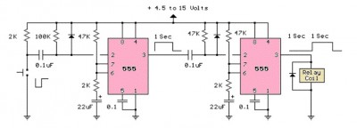
The LM555 timer circuit is similar to the previous design but incorporates two stages, allowing for control over both the pulse width and the delay. The LM555 timer is a versatile integrated circuit widely used in various timer, delay, pulse...
This is an audio-controlled lamp circuit. This circuit requires a low voltage input, such as from pre-amplifiers, tone control, or general audio line level output. The audio-controlled lamp circuit is designed to activate a lamp in response to audio signals....
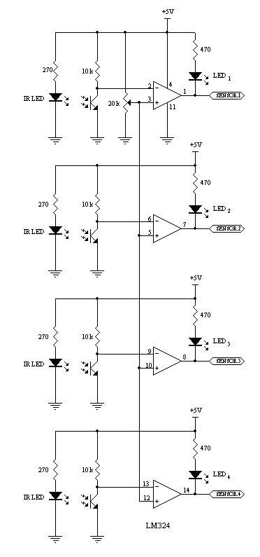
This robot utilizes two motors to control the rear wheels, while the single front wheel is free to move. It is equipped with four infrared sensors located on the underside to detect black tracking tape. When the sensors identify...
The basic clock circuit is similar to the binary clock and uses 7 ICs to produce the 20 digital bits for 12 hour time, plus AM and PM. A standard watch crystal oscillator (32,768) is used as the time...
The heating element is connected in series with two back-to-back 16 amp silicon-controlled rectifiers (SCRs), which are controlled by a small pulse transformer. This pulse transformer features three identical windings; two of these windings provide trigger pulses to the...
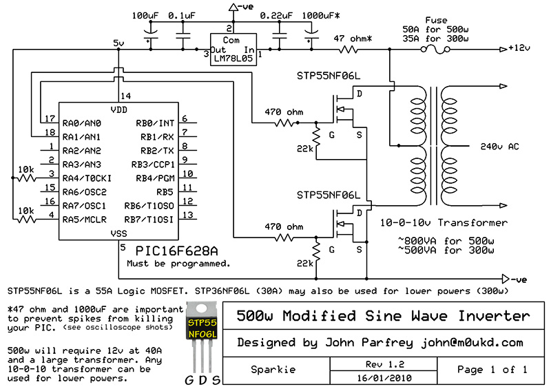
PIC controlled 500W Modified Sine Wave Inverter. The PIC16F628A is programmed to produce a logic 5V signal for 5ms at pin 17, followed by 15ms off. The described circuit implements a 500W modified sine wave inverter controlled by a PIC16F628A...
Warning: include(partials/cookie-banner.php): Failed to open stream: Permission denied in /var/www/html/nextgr/view-circuit.php on line 713
Warning: include(): Failed opening 'partials/cookie-banner.php' for inclusion (include_path='.:/usr/share/php') in /var/www/html/nextgr/view-circuit.php on line 713