
Structured PIC BASIC

The circuit design integrates multiple components and functionalities, showcasing the versatility of the PIC microcontroller platform. The use of the XCSB servo library allows for seamless control over multiple servos, enhancing the application potential in robotics and automation. The LCD interface provides real-time feedback, which is crucial for user interaction, while the keypad enables user input for control and security features. The incorporation of an ADC for analog input processing exemplifies the ability to interface with variable resistance devices, such as potentiometers, to create dynamic control systems. Furthermore, the RS232 interface programs illustrate the capability of the PIC microcontroller to communicate with other devices, facilitating data exchange and control commands. Overall, this circuit serves as a comprehensive platform for developing and testing various electronic applications, leveraging the capabilities of the PIC16F628 and PIC16F876 microcontrollers.This circuit shows the use of the XCSB servo library to control 4 RC servos. The demo runs on a 16f628 using the internal 4MHz oscilator. It uses 1 push button to select between servos and 2 push buttons to change the selected servos position. A 16x2 character LCD gives operator feed back while controlling the servos. The servo library can handle upto 20 servos on a 16f876. The circuit has additional resisters between the PIC and the LCD to allow in-circuit programming of the PIC using a programmer such as the wisp628 available from Connection points are clearly marked. This circuit shows the use of a 3x4 keypad and a 16x2 LCD connected to a 16f628. The 3x4 keypad is a cheap device using 12 switches aranged as a matrix. The interface uses 7 wires and connects directly to the PIC. The XCSB test program keypad-02. bas shows how trivial it is to read the keypad and display key presses on the LCD. A very simple modification would allow the program to accept PIN numbers and activate an electronic lock.
A precompiled ready to run executable is available as keypad-02. hex This circuit shows how to read an analog input using the built-in Analog to Digital Convertor (ADC) of the 16f876 The analog input is a 10K linear potentiometer (also know as a pot). The XCSB test program adc-pwm-876-001. bas reads the value of the pot (R6) using the built-in Analog to Digital Convertor (ADC) of the 16f876, displays it on the LCD and uses it as the setting for the PWM generator.
The speaker produces a tone corresponding to the value of the pot. Turning the pot changes the tone produced. Simple flashing LED program ready to run on minimal 16f628 circuit with internal oscillator - machine code executable in hex format ready to run (compiled from led-01. bas source) XCSB source file for LED flashing program with switch inputs for flash count. There is pause between flashes. Two switches are used to allow the user to select the number of flashes between pauses. Much more sophiticated version of led-02. bas using multiple tasks and background switch debouncing. Shows how to produce simple XCSB programs with very good user response. Simple LCD test program ready to run on minimal 16f628 circuit with internal oscillator - machine code executable in hex format ready to run (compiled from lcd-01.
bas source) XCSB source file to show simple user interface using two switches and an LCD. The switches perform an UP/DOWN function useful for setting values to control external hardware. This program shows switch debouncing and multitasking. XCSB source file similar to lcd-03. bas but showing how to greatly improve switch operation (i. e. single key press and autorepeat timings) by adding an extra task. Simple RS232 interface test program. This program sends one character per second via an RS232 interface to a terminal (or PC running terminal emulation software). If it receives a character from the terminal (or PC) it sends that character back instead of the original.
This allows both the sending and receiving side of the circuit to be tested. The program also flashs an LED to show that it is working correctly (in case data is not getting through on the RS232 interface) Simple RS232 interface test program ready to run on minimal 16f628 circuit with internal oscillator - machine code executable in hex format ready to run (compiled from rs232-01. bas source) This simple program accepts input using an RS232 interface and displays the input on an LCD display.
Otherwise this program operates as per rs232-01. bas (including the flashing LED). Simple RS232 interface test program ready to run on minimal 16f628 circuit with internal oscillator - machine code executable in hex format ready to run (compiled from rs232-03. bas source) XCSB source file to show simple user interface to control 4 RC servos. It uses 1 push button to select between servos and 2 push buttons to change the selected servos position.
The bu 🔗 External reference
Related Circuits

This optodetector measures the position of the ball by the amount of light transmitted by the infrared LED. It generates a linear signal across the small area of the detector, rather than simply providing an "on" or "off" output....

This is a simple 3-digit digital voltmeter. A PIC16F676 microcontroller is utilized to read analog signals (voltage) and display the value on a 3-digit 7-segment display. Similar principles can be applied to measure DC current using a parallel resistor...
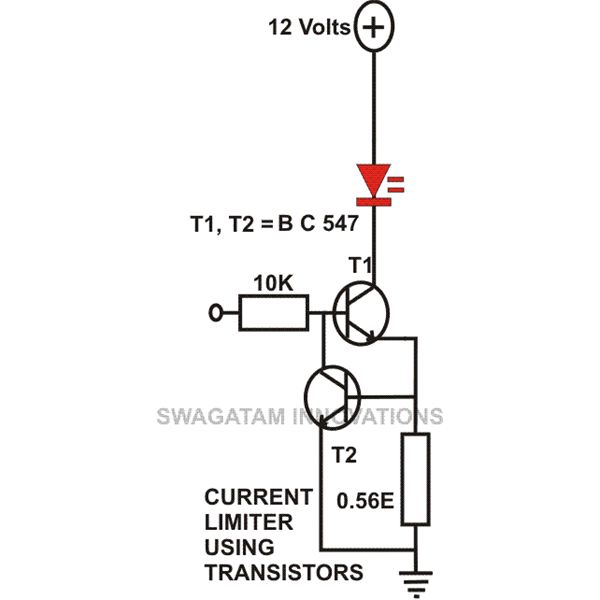
This article compiles small transistor circuits and configurations suitable for beginners, including current amplifiers, limiters, oscillators, and latches. A simple current amplifier circuit can be constructed using just a couple of NPN transistors. Additionally, two transistors and resistors can...

The days of arriving home at night and entering into darkness are finally over. This is a highly practical device, and it has been designed as a module. This device is intended to provide illumination upon entering a dark space,...
A versatile package containing numerous potential projects. This development board is designed for 28-pin PIC microcontrollers and includes a power supply circuit, a crystal oscillator circuit, an RS232 port, an ICSP/ICD port, and a 16x2 alphanumeric Supertwist LCD. The development...
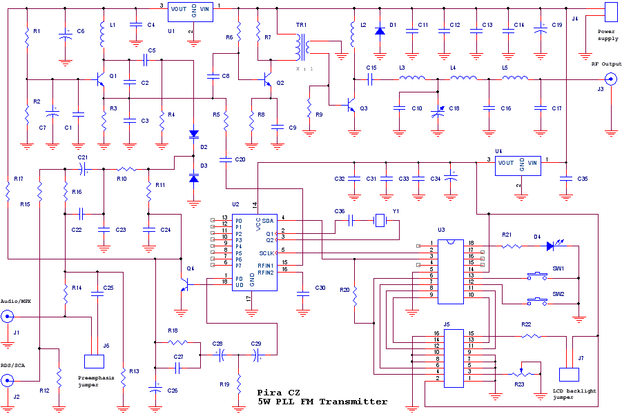
The transmitter includes RDS/SCA input and Audio/MPX input with optional preemphasis. It can be used with or without stereo encoder. Tuning over the FM band is provided by two buttons that control dual-speed PLL. The transmitter can work also...