
Schematic Diagram Basic Levitation and Magnetic Levitation Circuit Project

The optodetector circuit is designed to provide precise measurements of the ball's position by detecting variations in light intensity emitted by an infrared LED. The linear output from the detector allows for a more nuanced control signal compared to binary outputs. The comparator stage is crucial for determining the positional difference between the two optodetectors, which is then amplified to ensure sufficient signal strength for the subsequent stages.
In the context of the levitation toy, the integration of a permanent magnet and the electromagnetic coil creates a feedback loop that dynamically adjusts the magnetic force based on the ball's position. The NPN transistor acts as a key component in this feedback mechanism, allowing for rapid adjustments in current flow through the coil, thereby ensuring stable levitation. The use of a 9-volt power supply is essential for providing the necessary energy to drive the coil and maintain the magnetic field.
The circuit's ability to modulate the magnetic force in response to the ball's position is a practical application of feedback control systems, where the operational amplifiers play a vital role in maintaining stability and precision. By leveraging the high impedance and gain characteristics of op-amps, the circuit can effectively minimize errors and ensure that the levitation system operates smoothly. The overall design exemplifies the principles of electromagnetism and control theory, making it an educational tool for demonstrating fundamental concepts in electronics and physics.This optodetector measures the position of the ball by the amount of light transmitted by the infrared LED. This is a linear signal across the small area of the detector - it is not just "on" and "off". This circuit creates a control signal from the two optodetectors. It finds the difference between the two input voltages and amplifies it to get the ball`s position. This stage is often called a comparator. This circuit amplifies the control signal in preparation for the power output transistor. Why do we need this stage at all Because we reduced the whole signal by one-ninth in the speed-plus-position circuit. The point of the perpetual top levitation toy is simply that it continues spinning forever, and the challenge is to understand the driving mechanism.
The top is made of plastic, and contains embedded in it a small permanent magnet, oriented perpendicular to the spin axis of the top. The base contains a transistor and a coil with two windings, the assembly being driven by a 9-volt power supply.
A schematic of the electrical circuit is shown in the figure. As one pole of the magnet (say the south pole) approaches the coil, a current in induced in winding A, in such a direction as to make the base of the transistor (an NPN) go positive. That makes the emitter-collector current flow through winding B, in the opposite direction to A. The current through B is larger than that of A (due to the amplification of the transistor), so by Lenz`s law the magnet pole will be attracted to the coil.
This is a simple magnetic levitator circuit which suspends objects a set distance below an electromagnet. The physics behind it is to simply provide a magnetic force which equal and opposite to the gravitational force on the object.
The two forces cancel and the object remains suspended. Practically this is done by a circuit which reduces electromagnet force when an object gets to close, and increases it when the object is out of range. Operation of the electronics Board circuitry may be of interest to some students who use the Levitation/Critical Temperature kit.
Individual circuit functions may be understood and analyzed from the following explanations. Operational amplifiers (op amps) are characterized by two nearly ideal properties, which lead to a wide variety of applications. These properties are 1) high impedance between the non-inverting and inverting inputs and 2) high open loop gain.
Usually, both of these may be assumed to be infinite. Infinite impedance means no current flows between inputs, and infinite gain means that negative feedback will drive input voltage difference to zero. A variety of circuits can be analyzed using these two properties and Ohm`s law. 🔗 External reference
Related Circuits

Short circuits in the tracks, points, or wiring are nearly unavoidable when constructing or operating a model railway. Although transformers for model systems are designed with built-in bimetallic switches to protect against short circuits, the response time of these...
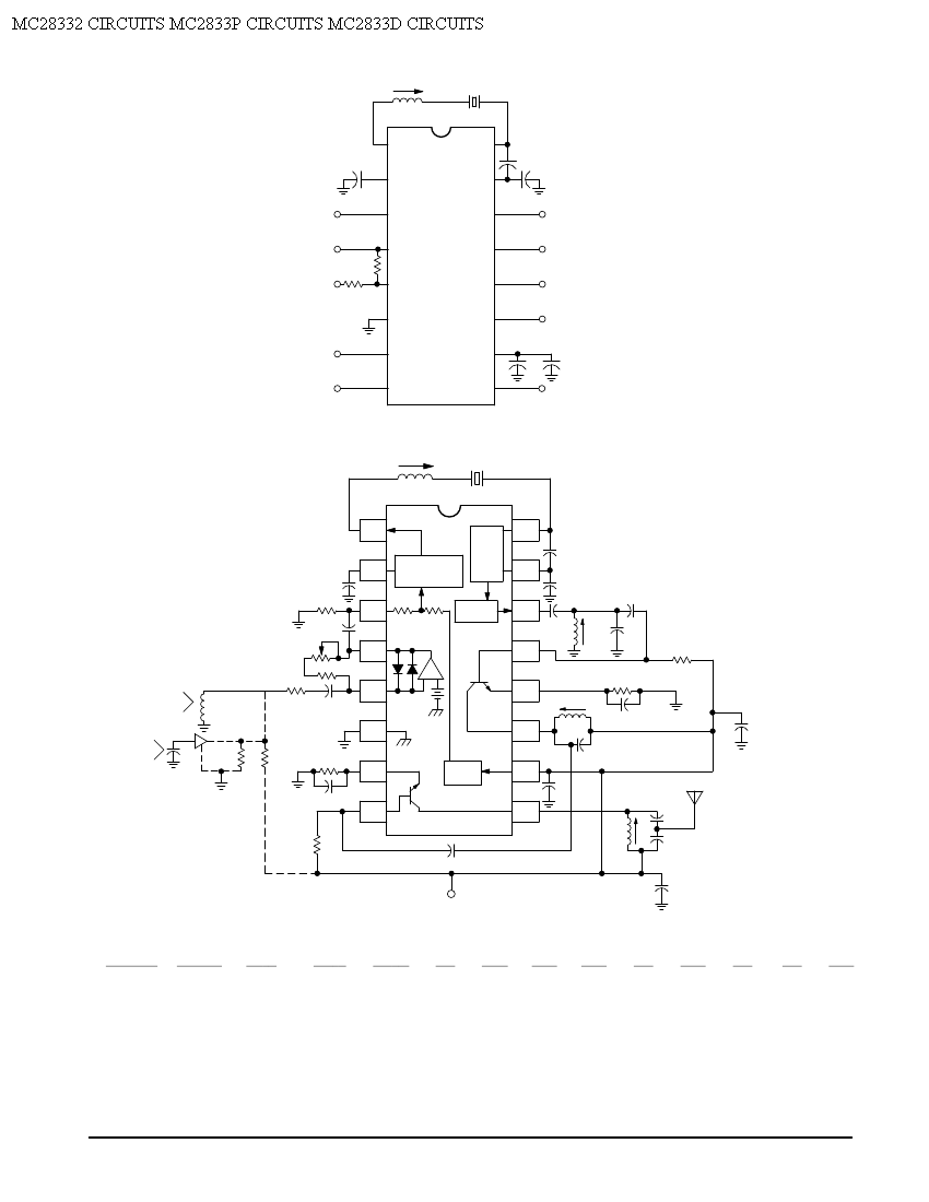
Crystal X1 operates in fundamental mode and is calibrated for parallel resonance with a load capacitance of 32 pF. The final output frequency is produced through frequency multiplication within the MC2833 integrated circuit (IC). The RF output buffer at...
This power supply unit (PSU) has been designed for high-current ham radio transceivers, providing approximately 20 Amps at 13.8V. It features a secondary output capable of handling currents from 15 mA up to a maximum of 20A. The unit...
This circuit is a simplified version of a commercial uninterruptible power supply (UPS). It provides a constant regulated output of 5 volts and an unregulated supply of 12 volts. The described circuit functions as a basic uninterruptible power supply, designed...
The electromagnetic RBI timer features a simple structure, is cost-effective, and is commonly utilized in high school physics experiments. However, a significant drawback of the electromagnetic RBI timer is the substantial errors it produces during experiments. This issue arises...
The SC41343 is designed as a type of infrared, ultrasonic, or RF remote control launch coding circuit. The internal circuit comprises a sequence generator, control logic circuit, 4-bit shift register, data extraction circuit, and latch circuit. Features include the...