
Superlinear FM (Frequency Modulator)
An FM modulator is an electronic device that encodes information in a carrier wave by varying its frequency in accordance with the amplitude of the input signal. This modulation technique is widely used in communication systems, including radio broadcasting, where audio signals are transmitted over radio frequencies.
In a typical FM modulator circuit, the core components include an oscillator, a modulating signal source, and a frequency deviation control mechanism. The oscillator generates a stable carrier frequency, which is then modulated by the input signal. The modulation index, which determines the extent of frequency variation in relation to the input signal's amplitude, can be controlled to optimize performance based on the specific application requirements.
The design of an FM modulator can vary significantly depending on its intended use. For synthesizers, the modulator may need to produce complex waveforms with specific harmonic content. In communication systems, the focus may be on achieving low distortion and high fidelity to ensure clear signal transmission. Additionally, the circuit may incorporate filters to eliminate unwanted harmonic frequencies and enhance the quality of the output signal.
In summary, an FM modulator is an essential subsystem in various electronic circuit designs, enabling the effective transmission of information by modulating the frequency of a carrier wave in response to an input signal. The design considerations and component selection are critical to achieving the desired performance characteristics for the specific application.Designing various electronic circuit system (synthesizer, modem, decoder, data converter, etc) of ten need a frequency modulator subsystem. An FM modulator is. 🔗 External reference
Related Circuits
The output of this circuit will be activated when a mix of two tones or frequencies is detected at the input. The frequency, denoted as f, is determined by the values of resistor R1 and additional components. This circuit is...
This doorbell circuit generates a low tone that transitions to a higher frequency. The total equivalent resistance connected between the base of Q1 and ground (Rbg), along with coupling capacitor C1, determines the frequency of the audio frequency (AF)...
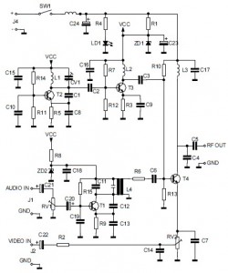
This is the circuit diagram of an audio/video modulator. The circuit converts audio and video signals into a UHF TV signal. It is designed to connect a video signal originating from a camera or other video source to a...

This is the circuit diagram of an audio/video modulator. The circuit converts audio and video signals into a UHF TV signal, allowing a video signal from a camera or other source to be connected to a standard TV set....