
Discrete Sliding Tone (Frequency Ramp) Doorbell
The described doorbell circuit utilizes a combination of resistors, capacitors, and diodes to achieve a unique audio output. The AF oscillator's frequency is primarily influenced by the total resistance Rbg, which is a function of R1, R2, and R3. The initial setting of R2 plays a crucial role in determining the starting frequency of the doorbell tone, ensuring it is both audible and pleasant to the user.
The charging behavior of capacitor C3 is critical in the operation of the circuit. As C3 charges through resistor R6, it reaches a threshold voltage that activates diode D1. Once D1 conducts, it modifies the resistance seen by the oscillator, allowing for a dynamic change in frequency. The interaction between Rbg and the diodes creates a feedback mechanism that results in a frequency sweep as the capacitor charges.
The inclusion of multiple diode paths is a sophisticated design choice that enhances the performance of the circuit. By providing two conduction paths with different biasing conditions, the circuit can maintain a linear transition in frequency even as the voltage increases. This feature not only improves the tonal quality of the output but also ensures that the transition between low and high frequencies is smooth and musically pleasing.
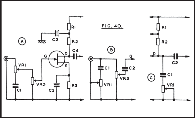
Overall, this doorbell circuit exemplifies a thoughtful integration of electronic components to create an effective and aesthetically pleasing audio output. The careful selection of resistors, capacitors, and diodes allows for a versatile design that can be easily adjusted to meet specific user preferences.This doorbell circuit produces a low tone that will slide up to higher frequency. The equivalent total resistance connected between the base of Q1 and ground (Rbg), and coupling capacitor C1 determines the AF oscillator`s frequency. The resistance (Rbg) is equal to (R2 R1)R3. Here is the schematic diagram of the circuit: The R2 is used to set the initial bias condition, adjusted to produce a pleasant low starting frequency doorbell tone. D1 will start to conduct when Capacitor C3 charge through R6 until it reaches D1 bias voltage level. Then the value of Rbg is paralleled by R4 and D1, and R5-D2-D3, and the values of diode`s equivalent resistance is gradually decreased as the C3 voltage ramp up. This decreasing resistance value make the output tone slides up in frequency. Two different diode path is provided to extend the linear area of diode conduction transition slope. With two path with different biases, after the single diode path has saturated, the second path provide further linear increase at higher voltage level.
🔗 External reference
Related Circuits
This is a basic 555 square wave oscillator designed to generate a 1 kHz tone for an 8-ohm speaker. In the circuit, the speaker is isolated from the oscillator by an NPN medium power transistor, which supplies more current...
This project has an impractical requirement or utilizes components that are no longer available. It is provided for reference or inspiration only and is considered unsupported. The project displays telephone numbers decoded from tones, specifically telephone touchtones or Dual...
The circuit operates from a 12V or similar power supply, with the option to adjust resistor R1 for higher voltage applications. There is significant flexibility in selecting values for components like capacitor C1. At point B, VR1 serves as...
The following diagram illustrates the circuit of a 20-band stereo graphic equalizer, which is designed to control audio signals within specific frequency ranges. This circuit should be connected prior to the amplifier circuit. For optimal performance, it is recommended...
The LM1036 is a DC-controlled circuit designed for adjusting bass, treble, balance, and volume in stereo applications, particularly in car radios, televisions, and audio systems. An additional control input enables the implementation of loudness enhancement. Four control inputs facilitate...
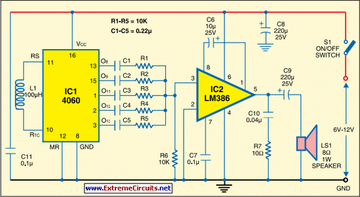
This multi-tone siren is beneficial for burglar alarms, reverse horns, and similar applications. It generates five distinct audio tones, making it significantly more attention-grabbing than a single-tone siren. The circuit is designed using the well-known CMOS oscillator and divider...