
switch mode voltage regulator with 85 efficiency
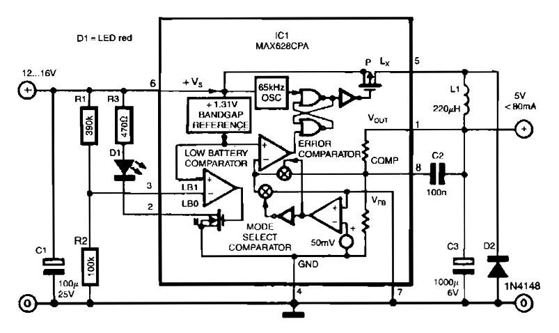
The MAX638CPA is a highly efficient switching regulator designed to step down higher DC voltages to a lower, regulated output voltage. In this configuration, the input voltage range of 12 to 16 volts is ideal for various applications, as it allows for flexibility in power supply options while ensuring that the output remains stable at 5 volts.
The nine external components typically include input and output capacitors, an inductor, and feedback resistors that set the output voltage. The input capacitor is crucial for stabilizing the input voltage and reducing ripple, while the output capacitor smooths the output voltage and minimizes voltage fluctuations. The inductor is a key component in the switching regulator, storing energy during the on phase and releasing it during the off phase, which helps maintain a continuous output current.
The feedback resistors are essential for adjusting the output voltage to the desired level, allowing for fine-tuning of the output to meet specific load requirements. The efficiency of 85% indicates that the circuit effectively converts the input power to output power with minimal losses, making it suitable for battery-powered applications where energy conservation is critical.
This circuit can be utilized in various electronic devices that require a reliable 5V power supply, such as microcontrollers, sensors, and communication devices. The simplicity of the design, combined with the efficiency of the MAX638CPA, makes it an excellent choice for engineers looking to implement a compact and reliable voltage regulation solution.The circuit is quite simple thanks to the use of MAX638CPA 5V CMOS Step Down Adjustable Switching Regulator IC. With this IC input voltage of 12 to 16 Vdc converted into direct voltage 5VDC. You can see here is only using 9 additional external components to complete the circuit. The schematic diagram come from circuit: Switch Mode Voltage Regulato r with 85% efficiency power supply. Go to that page to read the explanation about above power supply related circuit diagram. 🔗 External reference
Related Circuits
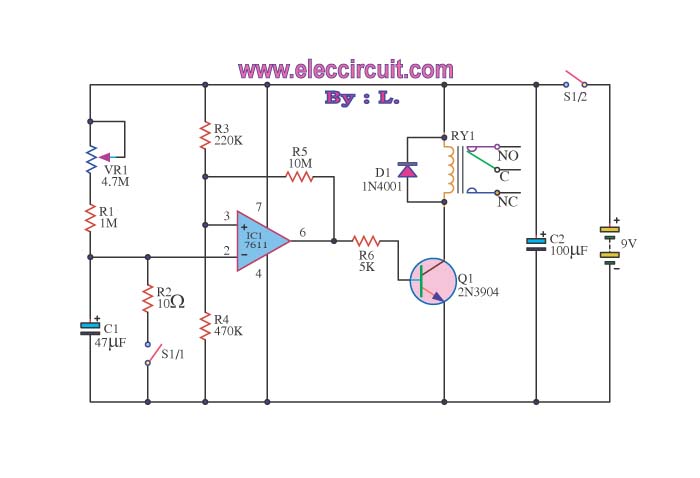
When switch S1/2 is activated, it powers the circuit C1, which utilizes the UA741 operational amplifier for voltage comparison. Pin 3 serves as the non-inverting input, while pin 2 is the inverting input. The voltage at pin 3 is...
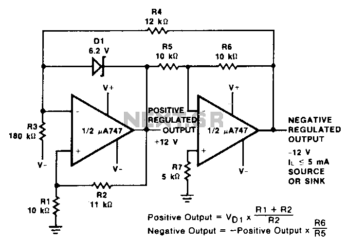
This reference utilizes an operational amplifier (op amp) to generate a negative output voltage that corresponds with the positive reference voltage. A pA747 dual op amp, or any similar device such as an LM1458 or two 1-A741 devices, can...
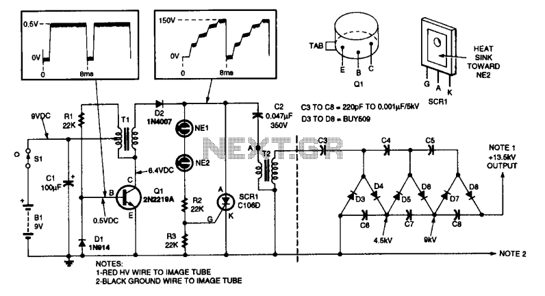
This high-voltage power supply features an inverter circuit centered around Q1, which generates 150-V pulses for the converter SCR1 and capacitor C2. The output from component ?2 produces a 4.5-kV pulse, which is further amplified by a voltage-tripler network...
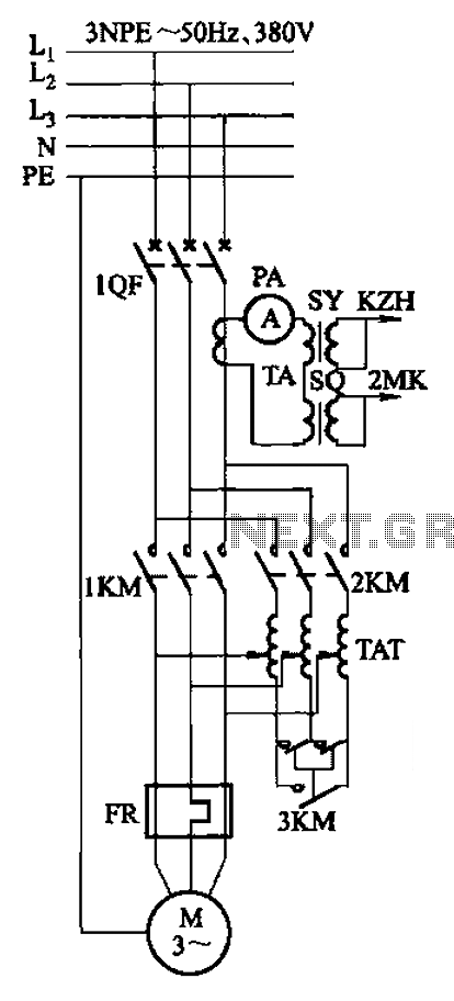
Autotransformer voltage starting, with an adjustable starting time of 30-60 seconds. It includes the SDJ electrode liquid level sensor of HJ-13 type, a pump control system box of HKD-21B type, 1MK level modules adopted by HKG-1SG type, 2MK start...
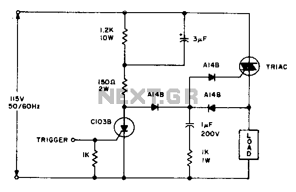
The triac will be activated at the beginning of the positive half cycle due to the current flowing through the 3 µF capacitor, provided that the C103 SCR is in the off state. The load voltage subsequently charges the...
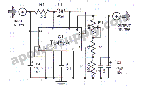
This voltage converter is constructed using the TL497A integrated circuit and is designed to convert an input voltage range of 5 to 12 volts into a higher output voltage range of 15 to 30 volts. This functionality is particularly...