
Triac zero voltage switching
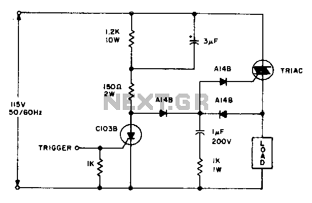
The circuit utilizes a triac for controlling power in AC applications, specifically designed to handle alternating current by switching on and off in response to the AC waveform. The operation begins with the positive half cycle of the AC signal, where the 3 µF capacitor plays a crucial role in delivering the necessary gate current to the triac. This gating action occurs only when the C103 SCR is not conducting, ensuring that the triac remains off until the appropriate conditions are met.
As the load voltage rises during this phase, it charges the 1 µF capacitor. This capacitor serves as a timing element that enables the triac to be triggered again during the next negative half cycle. The timing and control of this operation are vital for applications requiring precise power management, such as in lighting control or motor speed regulation.
The selection of a specific gate triac is important due to the III+ triggering mode, which is a method of controlling the turn-on point of the triac in relation to the AC waveform. This mode allows for finer control over the phase angle at which the triac is triggered, thus enabling efficient power delivery and reduced electrical noise.
In summary, the described circuit effectively utilizes capacitive coupling and controlled triggering to manage AC loads, ensuring that the triac operates efficiently across both halves of the AC cycle while accommodating the requirements of the III+ triggering mode.The triac will be gated on at the start of the positive half cycle by current flow through the 3 µf capacitor as long as the C103 SCR is off. The load voltage then charges up the 1 µF capacitor so that the triac will again be energized during the subsequent negative half cycle of line voltage
A selected gate triac is required because of the III+ triggering mode. 🔗 External reference
Related Circuits
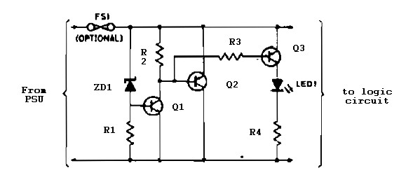
Logic overvoltage protection power supply. Refer to the designated page for an explanation of the power supply circuit diagram mentioned above. The logic overvoltage protection power supply is designed to safeguard sensitive electronic components from voltage spikes that could potentially...
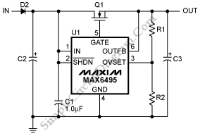
To protect downstream circuits from overvoltage conditions that occur during load-dump events or transients, the MAX6495, MAX6499, MAX6397, and MAX6398 can be utilized. The MAX6495, MAX6499, MAX6397, and MAX6398 are integrated circuits designed for overvoltage protection in various electronic applications....
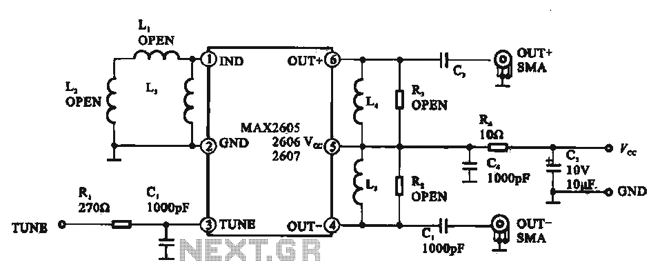
A low phase noise voltage-controlled oscillator circuit is presented, specifically integrated within the MAX2605-2609 voltage-controlled oscillator series. The circuit features a tuning voltage control terminal, allowing for adjustable oscillation frequency through a DC voltage input. The output of the...
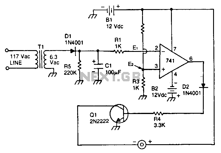
This circuit utilizes a type 741 operational amplifier (op amp) configured as a voltage comparator. One input of the 741 is connected to a reference voltage, sourced from a 12-V battery, via a resistor voltage divider. The voltage at...
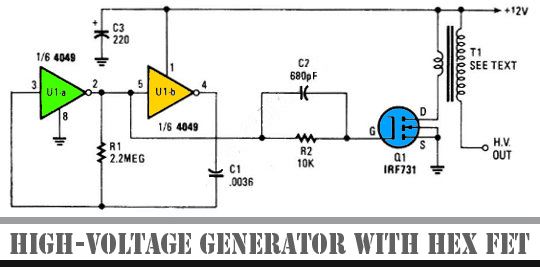
The schematic diagram below illustrates a high voltage generator circuit. This circuit employs a 4049 hex inverter configured as an oscillator, and it can utilize an ignition transformer from an automotive engine. A fly-back transformer may also be suitable....
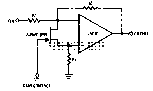
The 2N5457 functions as a voltage-variable resistor with a maximum RdS of 800 ohms. Given that the differential voltage on the LM101 is in the low millivolt range, the 2N5457 JFET exhibits linear resistance over several decades, offering excellent...
Warning: include(partials/cookie-banner.php): Failed to open stream: Permission denied in /var/www/html/nextgr/view-circuit.php on line 713
Warning: include(): Failed opening 'partials/cookie-banner.php' for inclusion (include_path='.:/usr/share/php') in /var/www/html/nextgr/view-circuit.php on line 713