
Tachometerless Motor Speed Control
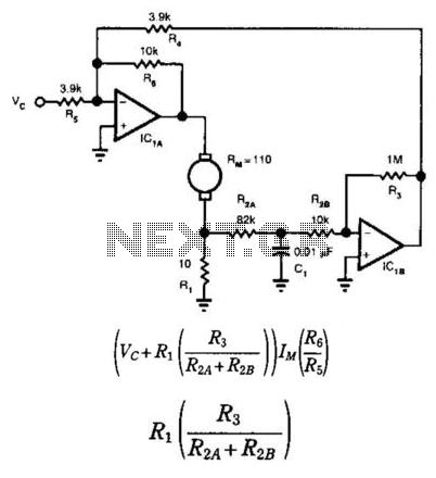
This circuit is designed for effective speed control of small motors in applications where precise regulation is essential. The use of a summing amplifier (IC1A) allows for the integration of multiple input signals, thereby facilitating the desired control over the motor's operation. The command voltage (Vc) is the primary input that dictates the motor's speed, while the motor current (IM) provides feedback necessary for maintaining stability and performance.
The relationship between the command voltage and the motor's counter emf is crucial, as it ensures that the motor operates efficiently within its specified limits. By configuring the motor's winding resistance and brush resistance (RM), the circuit achieves a balance that allows the command voltage to effectively counteract the back emf generated during motor operation. This balance is essential for achieving the desired speed regulation without the need for additional sensing devices such as tachometers.
Capacitor CI plays a vital role in compensating for any variations in the motor's performance, which may arise due to changes in load or supply voltage. This compensation is necessary to maintain consistent operational characteristics and prevent oscillations that could lead to instability in motor speed.
Furthermore, the selection of resistor R1 is critical, as its value should be set to 5 to 10% of RM's value. This ratio ensures that the feedback loop remains responsive while providing adequate damping to avoid excessive overshoot or oscillation in the motor's speed. The RM value can typically be referenced from the motor's specification sheet, allowing for accurate and reliable circuit design.
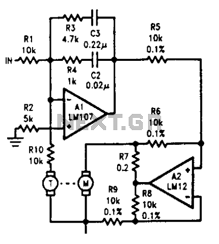
Overall, this circuit design is well-suited for applications requiring precise control of small motors, providing a straightforward solution that eliminates the need for complex feedback systems while maintaining efficiency and performance. This provides bidirectional speed regulation for small motors and requires no tachometer. The voltage th at summing amplifier IC1A applies to the motor"s windings equals: where Vc is the command voltage and IM is the motor current. If you set the motor"s winding resistance and brush resistance (RM) equal to: the command voltage will be proportional to the motor winding"s counter emf.
CI provides compensation. Set Rl"s value so that it equals 5 to 10% of RM"s value. You can generally find RM"s value in a motor"s spec sheet. 🔗 External reference
Related Circuits
This is a simple circuit that anyone can create for enjoyment. The project originated when there was an attempt to control a TV using the serial port of a computer. It took only a few minutes to grasp the...
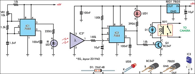
The IR detector (IC3) controls an LM 7555 CMOS timer (IC2) operating in monostable mode. When the beam is interrupted, IC2 is triggered, causing its pin 3 output to go high for approximately half a second. This action turns...
Good preparation. There is one suggestion to use RFM70 or RFM22 for RF communication. The RFM70 and RFM22 are low-power, high-performance RF transceiver modules designed for wireless communication applications. Both modules operate in the 2.4 GHz ISM band, making them...
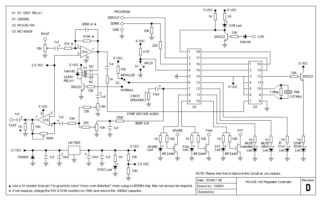
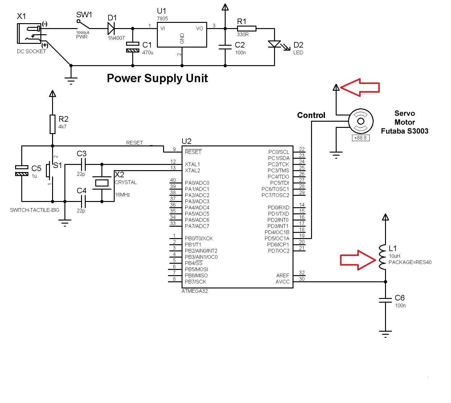
The project involves testing the capabilities of a PICAXE-18X chip operating at 4 MHz for a specific application. It includes designing the circuit, creating printed circuit board (PCB) artwork, etching the PCB, programming the PICAXE in BASIC, and connecting...
A photo-activated normally open relay is employed in a circuit that interacts with light. In this configuration, a photodiode is utilized to detect light levels. The photodiode exhibits high resistance in the absence of light. It is connected in...
The tachometer, mounted on the same shaft as the DC motor, functions as a generator, producing a DC output voltage that is proportional to the motor's speed. A summing amplifier, labeled as Al, manages its output to ensure that...
Warning: include(partials/cookie-banner.php): Failed to open stream: Permission denied in /var/www/html/nextgr/view-circuit.php on line 713
Warning: include(): Failed opening 'partials/cookie-banner.php' for inclusion (include_path='.:/usr/share/php') in /var/www/html/nextgr/view-circuit.php on line 713