
Motor-tachometer speed control
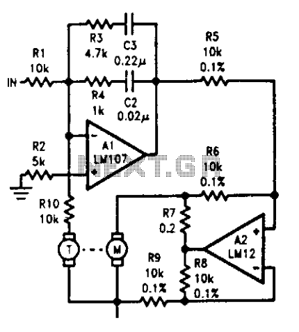
The described circuit integrates a tachometer with a DC motor to provide feedback on the motor's speed, enabling precise control over its operation. The tachometer generates a DC voltage that reflects the motor's speed, which is essential for closed-loop control in servo systems. The summing amplifier Al plays a crucial role in this feedback mechanism by ensuring that the output voltage from the tachometer is effectively inverted, allowing for proper error correction.
The design of the summing amplifier includes compensation techniques that are vital in maintaining stability within the control loop. By ensuring that the phase shift remains below 90° within the operational frequency range, the system can avoid instability and oscillations that could arise from excessive phase lag. The ability to substitute a power operational amplifier for Al provides flexibility in the design, allowing for direct motor drive when rapid response is less critical.
In the context of position control, the circuit can be adapted to function as a position servo by incorporating a method to measure the displacement of the motor shaft from a predetermined setpoint. This involves generating an error signal that indicates the difference between the actual position and the desired position. The servo system then works to minimize this error, effectively driving the motor to the correct position.
It is important to note that the tachometer's feedback is necessary not only for speed control but also for compensating the phase lag introduced by the error signal. The inherent 180° lag must be countered to ensure that the control system remains responsive and accurate. Therefore, the integration of the tachometer and the summing amplifier is essential for achieving both speed regulation and positional accuracy in servo applications.The tachometer, on the same shaft as the dc motor, is simply a generator. It gives a dc output voltage proportional to the speed of the motor. A summing amplifier, Al, controls its output so that the tachometer voltage equals the input voltage, but of opposite sign. With current drive to the motor, phase lag to the tachometer is 90°, before the second order effects come in.
Compensation on Al is designed to give less than 90° phase shift over the range of frequencies where the servo loop goes through unity gain. Should response time be of less concern, a power op amp could be substituted for Al to drive the motor directly.
Lowering break frequencies of the compensation would, of course, be necessary. The circuit could also be used as a position servo. All that is needed is a voltage indicating the sense and magnitude of the motor shaft displacement from a desired position. This error signal is connected to the input, and the servo works to make it zero. The tachometer is still required to develop a phase-correcting rate signal because the error signal lags the motor drive by 180°.
🔗 External reference
Related Circuits
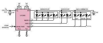
The LTC3205 is a highly integrated multidisplay LED controller. The part contains a high efficiency, low noise fractional step-up/step-down charge pump to provide power for both main and sub white LED displays plus an RGB color LED display. The...
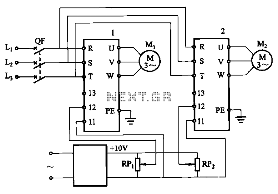
Adjust the potentiometers RPi and RPz to modify the speed of two motors. The circuit utilizes two potentiometers, designated as RPi and RPz, to control the speed of two separate motors. Each potentiometer is connected in a voltage divider configuration,...
Many of today's high-performance FPGAs, microprocessors, DSPs, and industrial/embedded subsystems require sequencing of the input power PS10 and PS11. Historically, this has been achieved through: i) discrete methods using comparators, references, and RC circuits; ii) expensive programmable controllers; or...
This may appear to be a highly detailed post; however, it is being written to assist others who are experiencing a similar frustrating search for 12V timers that possess functionalities comparable to those found in mains timers. The intention...
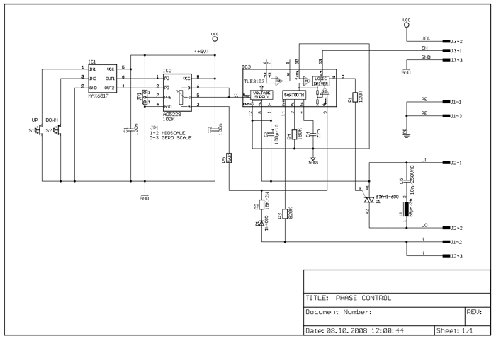
The following circuit illustrates a 2500W Phase Control Circuit Schematic. Features include a ground-tied trigger output that is disabled, and a low voltage input. The 2500W Phase Control Circuit is designed to regulate the power delivered to a load by...
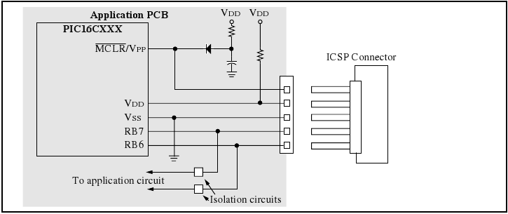
The programmer utilizes a serial signaling scheme to program the chip while it is in-circuit. The signaling is transmitted through the programming clock (PGC or ICSPCLK) and the programming data (PGD or ICSPDAT) pins. Additionally, the MCLR/VPP pin serves...