
tape content monitor
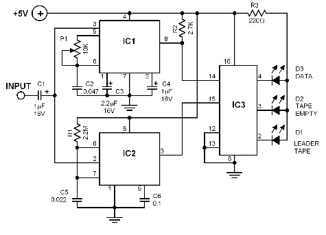
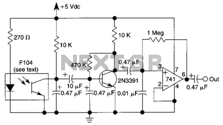
The circuit utilizes the tone decoder IC 567, which is designed to detect specific audio frequencies. It operates by analyzing the incoming audio signal from the cassette recorder, specifically looking for a pilot tone that indicates the presence of recorded data. The frequency of this pilot tone is adjustable via the potentiometer P1, allowing for fine-tuning based on the characteristics of the recorded material.
The timer IC 555 serves a dual purpose in this circuit. It not only helps in timing the response but also plays a role in signal processing. The capacitor C1 is critical as it couples the audio signal from the cassette output to the inputs of both the tone decoder and the timer. This ensures that both components can respond to the incoming signal simultaneously, enabling real-time analysis of the tape's contents.
In the event that no pilot tone is detected, the circuit behaves predictably. The tone decoder outputs a high signal, indicating an absence of recorded data, while the timer IC provides a low output. The IC 74145, which is a BCD (Binary-Coded Decimal) output driver, then activates its decimal output corresponding to the absence of a signal. This results in LED D2 illuminating, providing a visual indication to the user that the section of tape being analyzed is unrecorded.
This design effectively streamlines the process of locating specific programs on a cassette tape, allowing users to quickly identify recorded versus unrecorded sections. The combination of the tone decoder and timer IC, along with the visual feedback from the LEDs, creates a user-friendly interface for managing cassette playback and data retrieval.The capability to determine which part of the tape is empty and which part has a recorded data can help accelerate your work of looking for a certain program. The circuit uses a tone decoder IC 567 and a timer IC 555. The 567 IC decodes the pilot tone of each recorded program. The tone frequency to which this tone decoder reacts must be set with p otentiometer P1. To do this, play a cassette with a recorded data and within the first 2 to 10 seconds try to adjust P1 so that LED D1 lights up. If you did not get it at the first try, rewind the tape and start again from the beginning. The input of the circuit is connected to the output of the cassette recorder. The signal from the tape reaches the inputs of the tone decoder 567 and the timer 555 simultaneously through capacitor C1.
One of three things may possibly happen: First. No signal. The tone decoder 567 outputs a logic 1 (high) and the timer 555 outputs a logic 0 (low). IC 74145 activates decimal output 2. LED D2 lights up. 🔗 External reference
Related Circuits
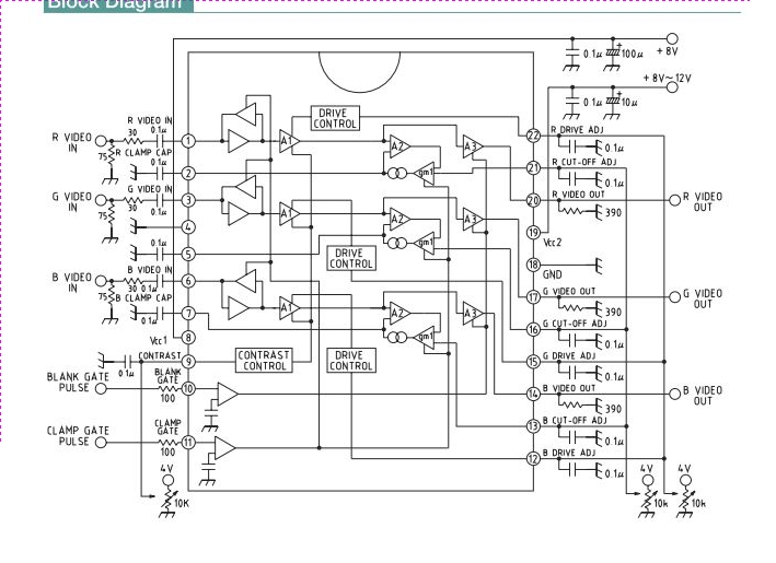
This integrated circuit (IC) is a wideband RGB video amplifier with DC control designed for monitors. It features three matched video amplifiers, a differential input comparator for brightness adjustment, and three matched DC components. The wideband RGB video amplifier is...
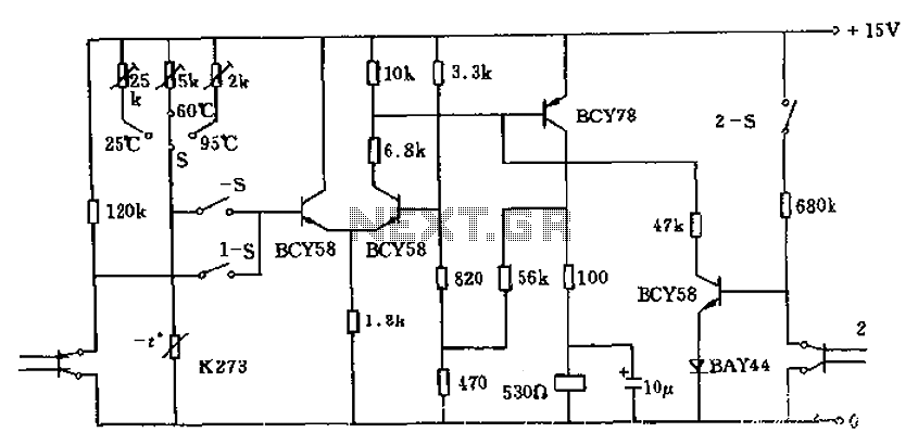
The circuit utilizes a thermistor (K273) to monitor temperature levels and control a relay based on the immersion of two sensor electrodes in a liquid. When the temperature reaches a predetermined threshold, the relay activates to heat the liquid....
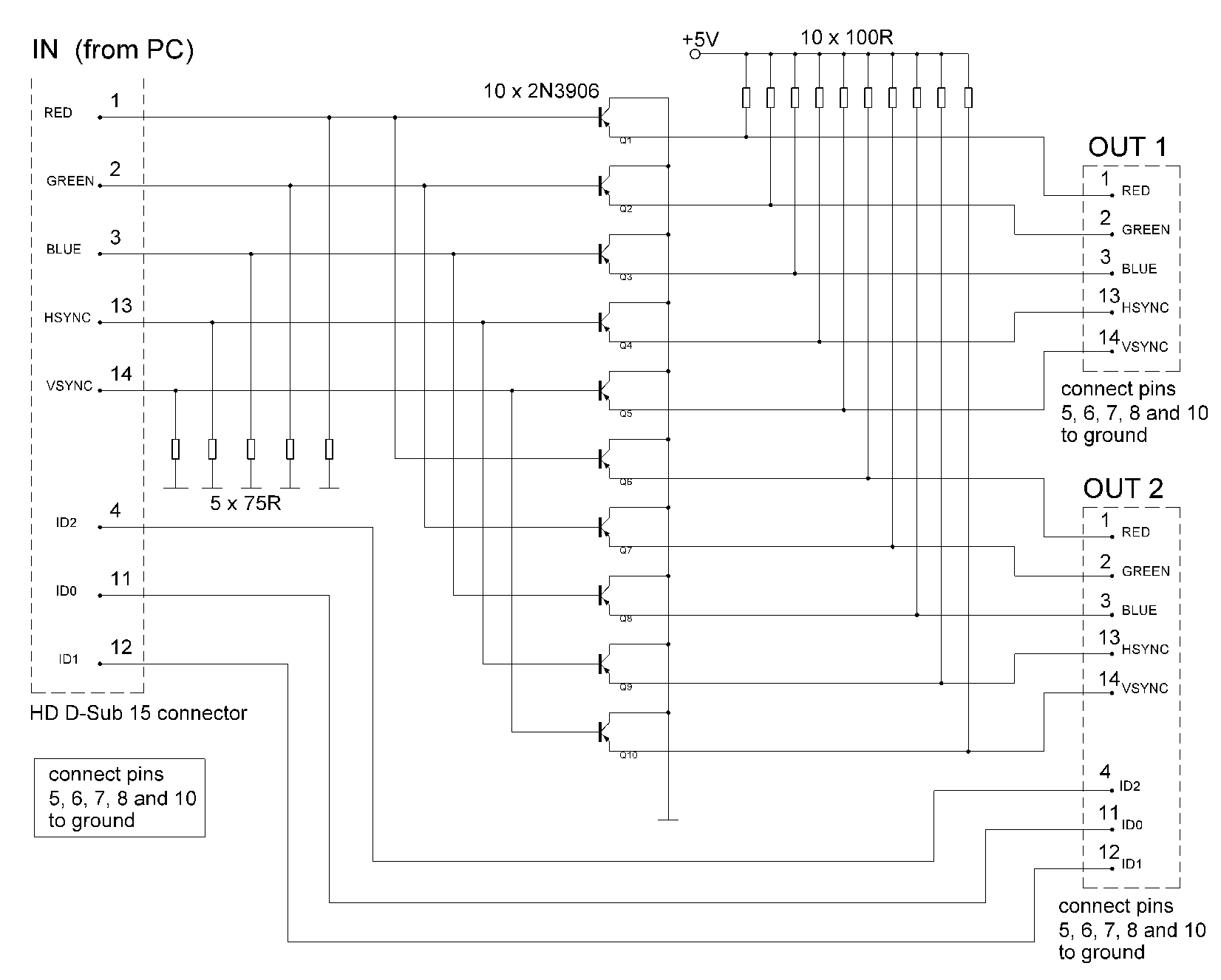
The signal sources in the analog output stage of the PC SVGA card are designed to present the correct impedance of 75 ohms on each line, utilizing five resistors. The input impedances of the transistors are sufficiently high to...
An infrared (IR) photodiode is employed to detect the IR reflectivity of the skin, which changes due to increased blood volume during heart contractions. This device captures a signal that correlates with the heartbeat. A transistor and operational amplifier...
This circuit is designed to detect tampering with a telephone line. It identifies if another telephone is connected, if there is a short circuit, or if the line is open. An audio alert and a flashing LED indicate the...
This device monitors sounds in a home or office when a telephone is called from a remote location. The described device functions as an audio monitoring system that activates upon receiving a telephone call. The core of this system typically...
Warning: include(partials/cookie-banner.php): Failed to open stream: Permission denied in /var/www/html/nextgr/view-circuit.php on line 713
Warning: include(): Failed opening 'partials/cookie-banner.php' for inclusion (include_path='.:/usr/share/php') in /var/www/html/nextgr/view-circuit.php on line 713