
Heartbeat Monitor Circuit
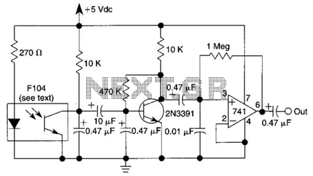
The infrared photodiode operates by converting light into an electrical signal. When the heart contracts, blood volume in the skin increases, leading to variations in IR reflectivity. The photodiode captures these variations, producing a small electrical signal that corresponds to the heartbeat.
To process this weak signal, a transistor is used as a switch or amplifier. The transistor can provide the necessary gain to elevate the signal strength, making it suitable for further processing. The operational amplifier, known for its high input impedance and low output impedance, is configured to amplify the signal from the photodiode. The op amp can be set up in a non-inverting configuration to ensure that the output signal is in phase with the input signal, further enhancing the signal quality.
The amplified signal can then be fed into logic circuitry, allowing for digital processing or triggering of other components in a system. Alternatively, the signal can be connected to an oscilloscope for visualization, enabling real-time monitoring of the heartbeat signal. This configuration is essential for applications in medical devices, fitness monitoring, and other health-related technologies where accurate heart rate detection is necessary. The design should also consider factors such as noise reduction and signal integrity to ensure reliable performance in various environments. An IR photodiode, which senses IR skin reflectivity as a result of increased blood volume during the periods that the heart forcibly contracts, is used to pick up a signal that is correlated with the heartbeat. A transistor and op amp raise this to a level suitable to trigger logic circuitry or to be displayed on a scope. 🔗 External reference
Related Circuits
Adding this combination audio circuit, as illustrated in figure 14-38, to the automatic rhythm generator of electronic musical instruments fulfills the players' demand for incorporating drum and cymbal audio, enhancing the overall performance effect. The diagram indicates that the...

This circuit is designed to control the mains voltage by switching it on and off at intervals ranging from just under a second to up to 10 minutes. It is particularly useful for testing mains-operated equipment over extended periods...
Low-cost water pump controller circuit. The sensors used in the circuit can be any two conductive probes, preferably resistant to electrolytic corrosion. For example, a suitably sealed audio jack can be employed as the sensor. The automatic pump controller...
The SN75604, which features input control logic and requires only a single supply rail, can be utilized in light activation sensors and alarm drivers. The device's Vqq and enable inputs are connected to a voltage lead from the light...
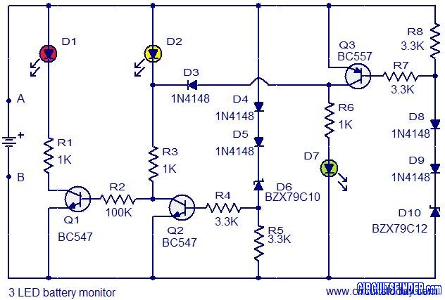
This is the circuit diagram of a 3 LED bar graph type battery monitor circuit that is ideal for monitoring the voltage level of an automobile battery. When battery voltage is 11.5V or less, transistor Q1 will be on...
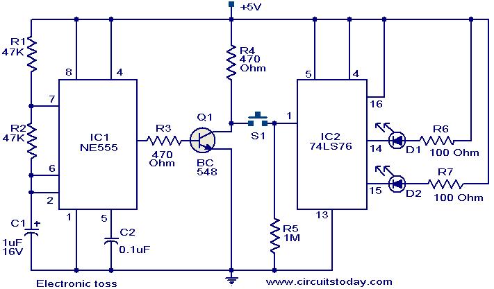
The circuit described can be utilized for tossing a coin, serving as a random generator for head or tail outcomes. This circuit is applicable in various games where a coin toss is required to initiate play. It employs two...