
Tape recorder position indicator-controller
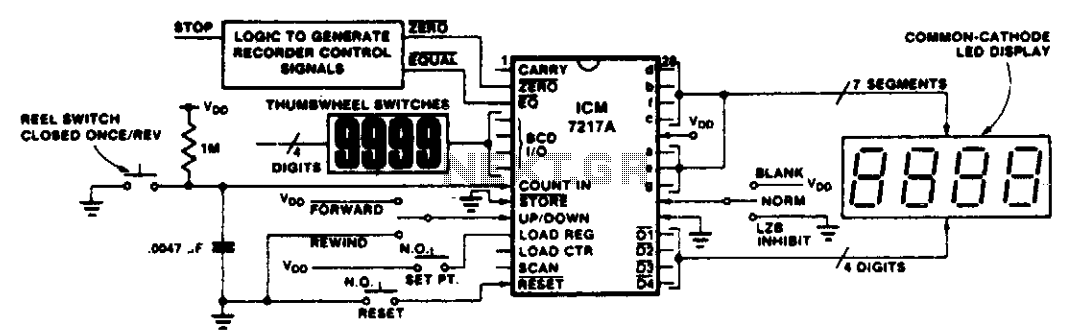
To prevent the tape from becoming loose on the reel during rewind, a leader tape should be used. By resetting the counter at the starting point of the tape, a few feet from the end of the leader, the ZERO output can be activated to stop the recorder during rewind, ensuring that the leader remains on the reel. A 1-ohm resistor and a 0.0047 µF capacitor on the COUNT INPUT create a time constant of approximately 5 ms to debounce the reel switch. The Schmitt trigger on the COUNT INPUT of the ICM7217 conditions the signal before it is sent to the counter. This method can also be applied to debounce switch closure inputs in various other applications.
The circuit design employs an up/down counter configuration, specifically utilizing the ICM7217 integrated circuit, which is well-suited for precise counting applications. The LOAD REGISTER serves as a temporary storage for the desired count value, which can be programmed to correspond with specific tape positions. The EQUAL output provides a logical high signal when the counter value matches the value stored in the LOAD REGISTER, effectively signaling the control logic to execute the stop command for the tape recorder.
The ZERO output is crucial for ensuring that the tape recorder does not exceed the designated stopping point during rewind, thus preserving the integrity of the tape. The combination of the 1-ohm resistor and the 0.0047 µF capacitor on the COUNT INPUT is critical for filtering noise and preventing false triggering of the counter. This debounce circuit is particularly important in applications where mechanical switches are involved, as it enhances the reliability of the signal by eliminating spurious transitions that could lead to erroneous counts.
The inclusion of a Schmitt trigger on the COUNT INPUT enhances the robustness of the circuit by providing hysteresis, which further stabilizes the counting process. This design can be adapted for various applications that require precise control and monitoring of position, making it versatile for both consumer electronics and industrial automation scenarios.This circuit is representative of the many applications of up/down counting in monitoring dimensional position. In the tape recorder application, the LOAD REGISTER, EQUAL, and ZERO outputs are used to control the recorder.
To make the recorder stop at a particular point on the tape, the register can be set with the stop at a particular point on the tape, the register can be set with the stop point and the EQUAL output used to stop the recorder either on fast forward, play or rewind. To make the recorder stop before the tape comes free of the reel on rewind, a leader should be used. Resetting the counter at the starting point of the tape, a few feet from the end of the leader, allows the ZERO output to be used to stop the recorder on rewind, leaving the leader on the reel.
The 1 ohm resistor and .0047 µ¥ capacitor on the COUNT INPUT provide a time constant of about 5 ms to debounce the reel switch. The Schmitt trigger on the COUNT INPUT of the ICM7217 squares up the signal before applying it to the counter.
This technique may be used to debounce switchclosure inputs in other applications. 🔗 External reference
Related Circuits
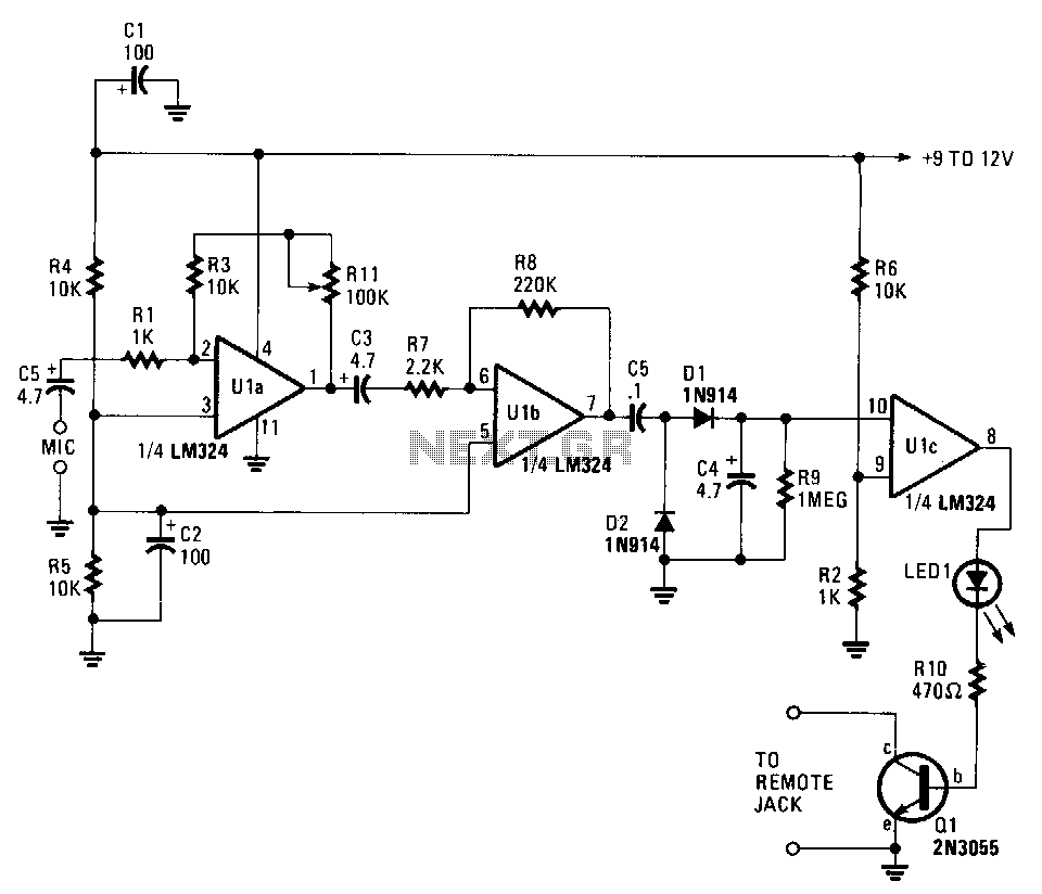
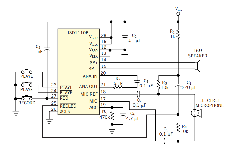
A voice sound recording circuit is desired, which, when triggered, will play the recorded sound through an amplifier circuit. The proposed voice sound recording circuit can be designed using a microcontroller or dedicated audio recording ICs, along with an amplifier...
Amateurs do not have to miss the action while away from the rig. This circuit activates a tape recorder whenever the receiver's squelch is broken. After signal loss, the recorder will turn off following a slight delay. The described circuit...
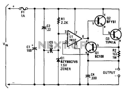
A regulator enables the powering of a 7.5-V cassette recorder or other devices from a 12-V DC automotive system. The circuit can provide approximately 600 mA of current. Q3 requires a heatsink due to its potential to dissipate up...
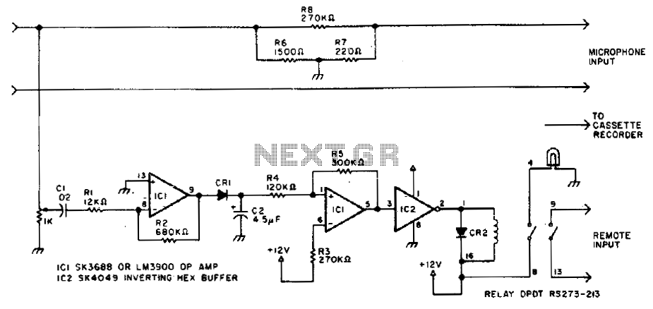
This circuit can cause a cassette recorder to automatically turn on and record when a sound or noise is present. Another use is when the sound-activated switch is used to turn on a cassette player, allowing it to function...
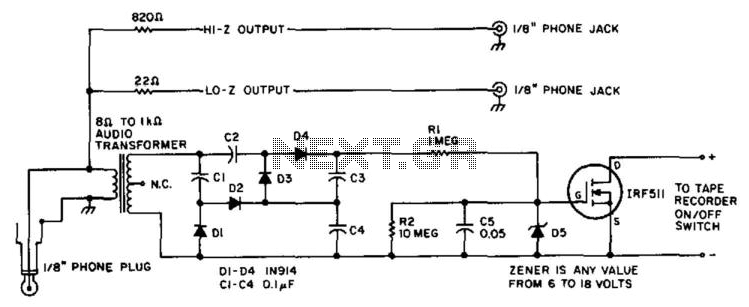
A tape recorder can be controlled by rectifying the audio input and driving an IRF511 power MOSFET to switch the tape recorder on when audio is present. This circuit was used with a communications receiver to record intermittent transmissions,...
The original input data describes a common situation in many companies where a single type of telephone is purchased for all employees. This is often done to take advantage of quantity discounts. However, this can lead to problems as the...
Warning: include(partials/cookie-banner.php): Failed to open stream: Permission denied in /var/www/html/nextgr/view-circuit.php on line 713
Warning: include(): Failed opening 'partials/cookie-banner.php' for inclusion (include_path='.:/usr/share/php') in /var/www/html/nextgr/view-circuit.php on line 713