
Automatic tape recording
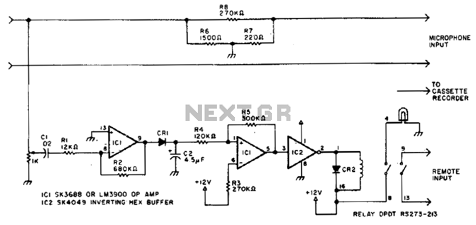
The described circuit serves as an automatic tape recorder activation system designed for amateur radio operators. It utilizes the principle of squelch detection, which is a common feature in radio receivers that suppresses background noise when no signal is present. When the receiver detects a signal strong enough to break the squelch, it sends a control signal to the tape recorder, activating it to begin recording.
The circuit typically includes a comparator or a transistor switch that monitors the output of the receiver. When the audio signal exceeds a predetermined threshold, the comparator triggers the tape recorder. This activation mechanism ensures that only relevant audio is captured, reducing unnecessary recording of silence or noise.
To manage the shutdown of the recorder, a timing circuit is integrated, which often consists of a resistor-capacitor (RC) network. This network introduces a slight delay before the recorder turns off after the signal is lost. The delay allows the operator to capture any trailing audio that may occur after the initial signal has ceased, ensuring that important communications are not missed.
Overall, this circuit enhances the functionality of amateur radio setups, allowing operators to engage in activities away from their rigs without losing important transmissions. The design can be further optimized through the selection of components to tailor the sensitivity of the squelch detection and the duration of the delay, depending on the specific requirements of the user.Amateurs don"t have to miss the action while away from the rig. This circuit turns on a tape recorder whenever the receiver"s squelch is broken After signal loss, the recorder will shut off following a slight delay,. 🔗 External reference
Related Circuits
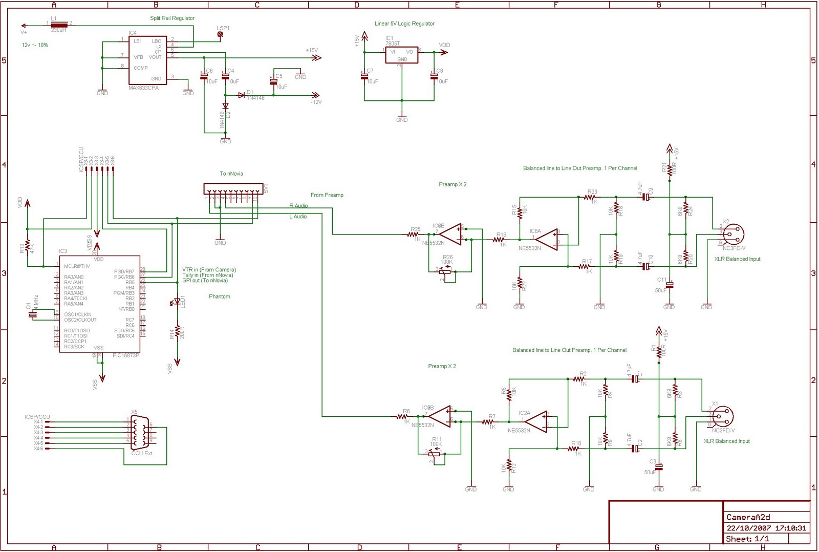
This is an ongoing project focused on creating a circuit to interface the nNovia QC120 A2D2 recorder with a Sony DXC-325P camera equipped with a CA-325P studio back. The final design is still in progress. A circuit based on...

This project involves an automatic room light controller with a bidirectional visitor counter using a microcontroller. It is designed to manage room lighting and accurately count the number of individuals present. When a person enters the room, the counter...
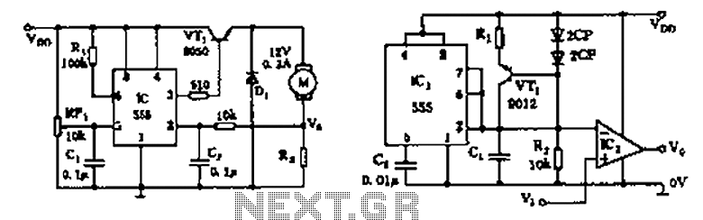
The circuit consists of a 555 motor automatic governor configuration. It includes flip-flops, a 555 timer, and a switching tube. A sampling circuit is formed by connecting R7 and the motor in series. RP1 is used to control the...
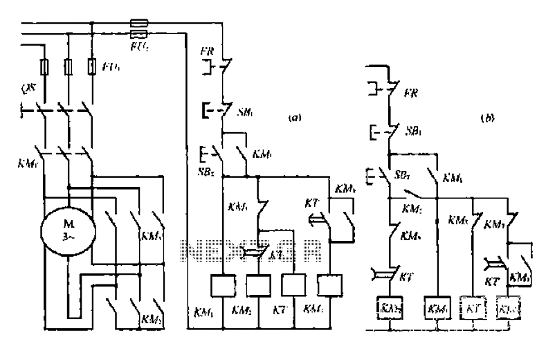
A star-delta switch is utilized for starting circuits, commonly depicted in Figure I-5 (a) of the knife wiring. While this method is effective, it poses security risks. When the motor starts, it can create significant voltage fluctuations that may...
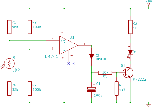
This electronic breadboard circuit for beginners in electronics activates an LED automatically when the ambient light level falls below a specific threshold. This circuit utilizes a light-dependent resistor (LDR) as the primary sensor to detect ambient light levels. The LDR...
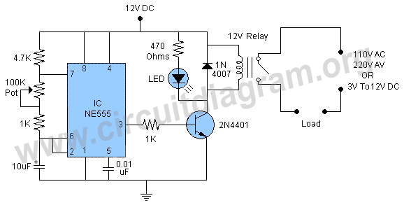
The circuit operates continuously, turning on and off. It utilizes the widely recognized NE555 timer IC, known for its versatility in various electronic applications. In this configuration, the IC is set up as an astable multivibrator. A 12-volt relay...