
Tech Gear Multi-Voice Changer
The Voice Changer circuit is designed to manipulate audio signals captured from a microphone and modify them based on user-selected effects. The microphone serves as the primary input source, converting acoustic signals into electrical signals. The switches allow users to select different voice effects, influencing how the audio signal is processed.
Upon receiving the input from the microphone, the signal is routed to an operational amplifier (OpAmp). This component is crucial for amplifying the weak audio signal to a level suitable for further processing and output. The OpAmp is configured to provide gain, which enhances the overall volume of the output sound.
The circuit employs a frequency modulation technique to achieve various voice effects. For basic effects like low pitch and high pitch, the circuit utilizes simple frequency shifting methods. When low pitch is selected, the circuit reduces the frequency of the input signal, while high pitch raises it.
In robotic mode, the circuit incorporates a more complex modulation technique. It rapidly oscillates the frequency of the signal between low and high values, creating a synthetic robotic sound. This effect is achieved by using a combination of oscillators and filters that modify the frequency characteristics of the signal in real-time.
The output of the circuit is then sent to a speaker, which converts the amplified electrical signal back into sound waves. The final output frequency, which varies depending on the selected effect, can be referenced in the accompanying table, detailing the specific frequency ranges associated with each voice effect. This comprehensive system allows for versatile sound manipulation, catering to various audio applications and user preferences.The Voice Changer has two different inputs, the microphone and the switches. The Voice Changer then outputs a signal to an OpAmp to amplify the signal being sent to the speaker. The frequency of this signal is changed depending on what voice effect is turned on. The more simple voice effects such as low pitch and high pitch only change the frequen cy up or down. When the device is in robotic mode the signal changes from a low frequency to a high frequency and oscillates back and forth to create the robotic sound effect. The table below shows the frequency of the signal output to the speaker. 🔗 External reference
Related Circuits
The objective of this project is to develop a multi-effect guitar processor capable of altering the tonal characteristics of a guitar. This device aims to provide a wide range of unique sounds, enhancing the entertainment value for users. The...
The following circuit illustrates a Three Phase Auto Changer Circuit Diagram. This circuit utilizes the 2N2222 transistor. Features include a transformer. The Three Phase Auto Changer Circuit is designed to automatically switch between different phases in a three-phase power system,...
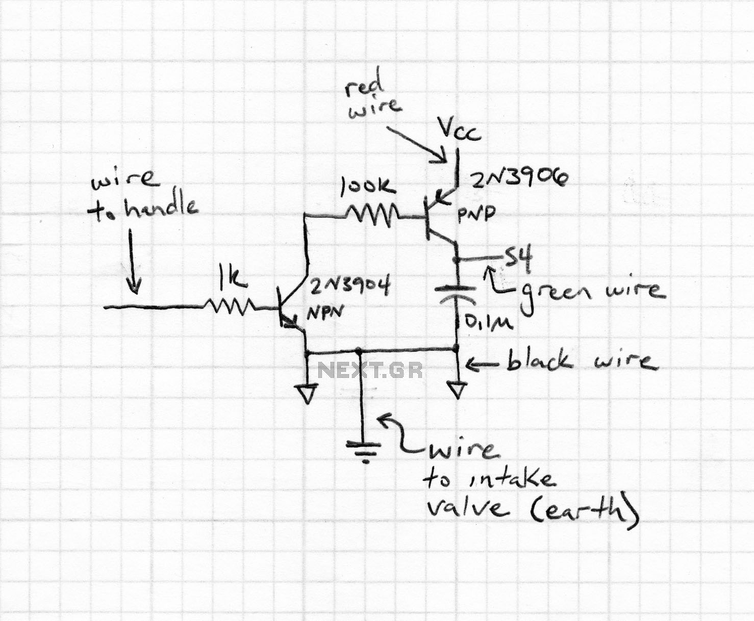
The telemetric physiologic monitors transmit measurements of bodily functions from beneath the skin of a live animal to a receiver beneath the animal's cage. The smallest transmitters the company produces are known as "mouse" transmitters, which garnered particular interest...
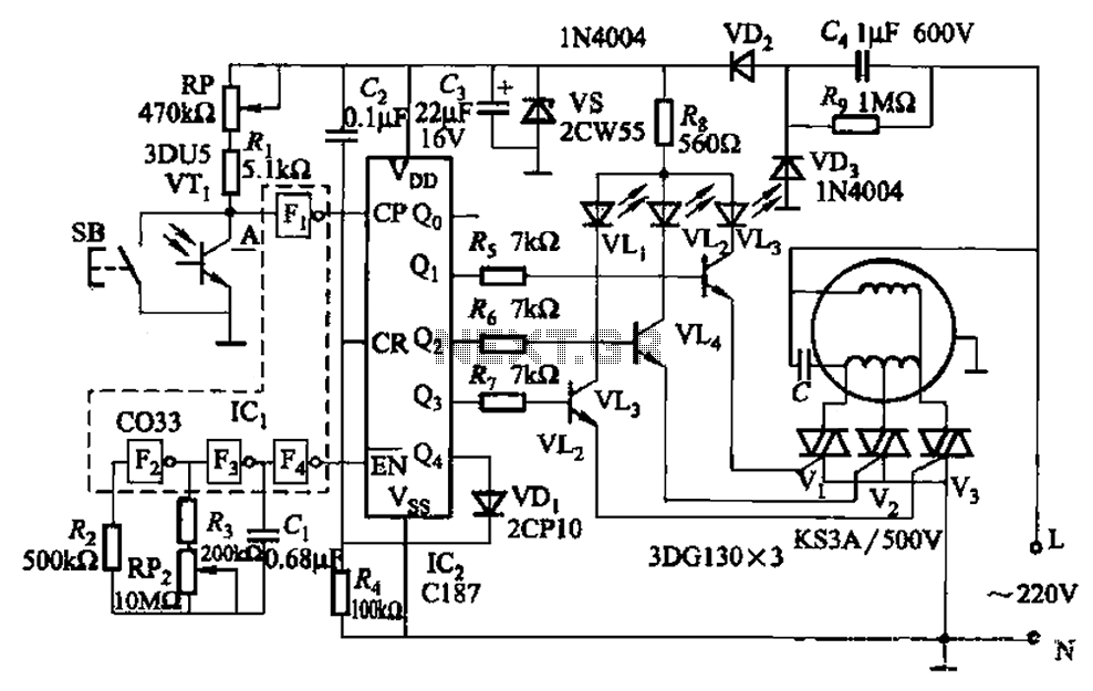
The circuit depicted in Figure 3-5 can be controlled manually using button SB or automatically via light detection using phototransistor VTj. When light from a flashlight is detected by phototransistor VTj, the fan will activate, adjusting its speed automatically...
Various circuit combinations were initially tested using alligator clips and different code interactions. The circuits were designed to turn on either individually and sequentially (A, B, C) or to turn on sequentially while remaining lit (A, AB, ABC). Blinking...
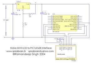
This project demonstrates the interfacing and operation of the Nokia 3310 LCD using the PIC16F628 microcontroller. The programming is executed in Hi-Tech C, with the character table incorporated within the source code. The Nokia LCD features a resolution of...