
Fans can light three-gear speed control circuit
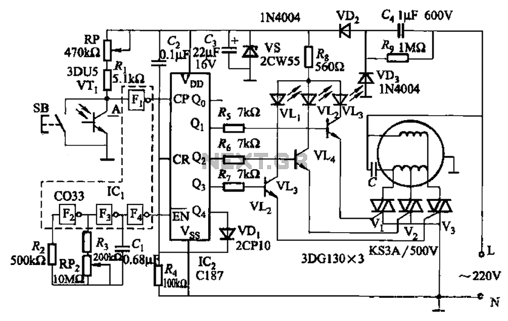
The circuit operates in two modes: manual and automatic. In manual mode, the user can control the fan's operation directly through button SB. This allows for immediate adjustment of the fan speed according to user preference. In automatic mode, the circuit uses a phototransistor, which senses ambient light levels. When a flashlight beam is directed at phototransistor VTj, it triggers the circuit to engage the fan, which then cycles through its speed settings in a predetermined sequence.
The CMOS hex inverter Icl is crucial for processing signals within the circuit. It takes the output from the phototransistor and inverts it, ensuring that the subsequent stages of the circuit receive the correct logic levels. The resistor-capacitor (RC) network connected to the inverter serves as a timing mechanism, generating clock pulses that dictate the timing of the fan's speed adjustments.
The integrated circuit Icz operates as a decimal counter and timing decoder, translating the clock pulses into control signals for the transistors VTz to VT4. These transistors act as switches, allowing current to flow to the TRIACs Vl to V3, which regulate the power delivered to the fan motor. The TRIACs are essential for controlling the fan speed by adjusting the power delivered based on the control signals from the integrated circuit.
In summary, this circuit design effectively combines manual and automatic control of a fan, utilizing light detection to enhance user convenience while maintaining precise control over fan speeds through a well-structured electronic design. The integration of CMOS technology, timing circuits, and power control devices exemplifies a sophisticated approach to fan speed regulation in various lighting conditions. Circuit shown in Figure 3-5. It can be manual (button SB) and light control (phototransistor VTj). When the light of a flashlight quasi VTi, fans will turn on the operation, an d sub slow, medium, fast three times a block is automatically adjusted. A CMOS hex inverter Icl (door F2-F4) and resistance, capacitance circuit clock pulse generator. By an integrated circuit Icz decimal counting/timing decoder transistor VTz ~ VT4, TRIAC Vl-V3 wind speed fan and other components (gear) switch circuit.
Related Circuits
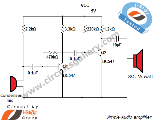
The output of the condenser microphone is coupled through a 0.1 µF coupling capacitor, which serves to eliminate DC components from the audio signal. Transistor Q1 is configured in a collector-to-base biasing mode, achieved with a 470kΩ resistor. This...
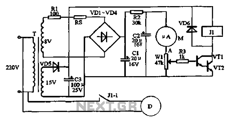
An automatic humidifier can be utilized for humidity control in households, hatcheries, poultry farms, or juvenile poultry houses. When the humidity level falls below 50%, the automatic humidifier activates to maintain a specific humidity level that is beneficial for...
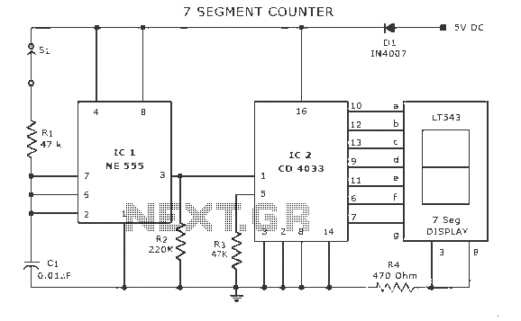
A display counter circuit is illustrated through a diagram featuring a seven-segment display controlled by the counter IC CD4033. This counter circuit is designed to visually represent incremental counts, enhancing its appeal for integration into various applications. An astable...

This circuit is designed for an LM1893 power line modem, which facilitates information transfer between remote locations using the power mains. The LM1893 serves as a power line interface for half-duplex (bi-directional) communication of serial bit streams employing various...
This circuit is a simple ultraviolet light that can be powered by a 6 volt battery or power supply (such as the power supply on the "Circuits" page) that is capable of supplying 1 or more amps. The described circuit...
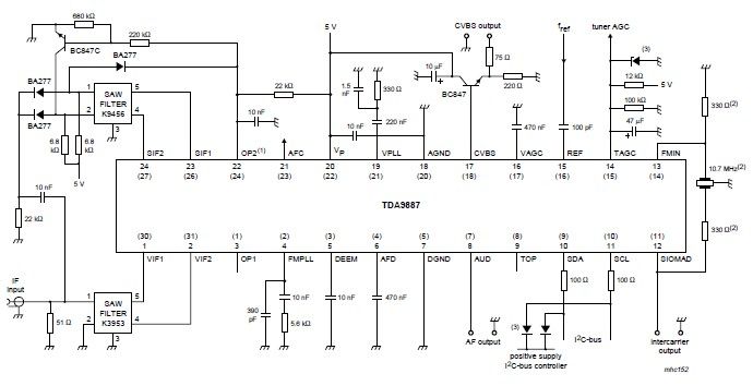
The integrated circuit (IC) is a multistandard vision and sound intermediate frequency (IF) phase-locked loop (PLL) demodulator that operates without the need for alignment. It supports multiple television standards, including PAL, SECAM, and NTSC, and is capable of handling...
Warning: include(partials/cookie-banner.php): Failed to open stream: Permission denied in /var/www/html/nextgr/view-circuit.php on line 713
Warning: include(): Failed opening 'partials/cookie-banner.php' for inclusion (include_path='.:/usr/share/php') in /var/www/html/nextgr/view-circuit.php on line 713