
Telephone Intercom Circuit
The intercom system described employs dual-modular wall jacks, which are standard connectors commonly used in telecommunications. The use of these jacks allows for easy connectivity and installation, particularly in residential settings where existing telephone wiring can be repurposed.
The circuit typically consists of two main components: the intercom units and the dual-modular wall jacks. Each intercom unit is equipped with a microphone and a speaker, enabling two-way communication. The dual-modular wall jacks serve as the interface points where the intercom units connect to the existing telephone wiring.
To install the system, the existing telephone cables, which usually contain multiple pairs of wires, can be utilized. The intercom units are connected to the appropriate pairs of wires at each wall jack. This setup not only simplifies the installation process but also minimizes the need for additional wiring, making it a cost-effective solution for home communication.
The intercom system can be powered through the existing telephone line, eliminating the need for separate power supplies. This feature enhances the convenience of the installation, as it reduces the complexity and potential points of failure in the system.
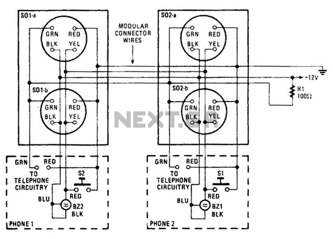
In summary, the intercom using dual-modular wall jacks is a practical solution for home communication, leveraging existing infrastructure to provide a straightforward installation process. The design ensures that users can easily communicate across different rooms without the need for extensive modifications to their home wiring. An intercom using dual-modular wall jacks is shown in this circuit. If the wires are available in the home telephone cable, this system can be installed with little trouble. 🔗 External reference
Related Circuits
The TX05C-R infrared surveillance alarm circuit is designed for monitoring walls, windows, doors, and various restricted areas. When an intrusion occurs, the alarm activates to enhance security. The circuit comprises a transmitter module, a receiver module, a time-base circuit,...
The circuit is capable of enhancing the system power factor to a value exceeding 0.99. It effectively reduces the waveform distortion of the input supply current, ensuring compliance with GB15144 standards, with a distortion index lower than level L....
This is a 25-watt basic power amplifier designed for ease of construction at a reasonable cost. It outperforms the standard STK module amplifiers commonly found in mass-market stereo receivers today. The design was initiated to create a 25-watt amplifier...
The circuit diagram focuses on the research and design features applied to mobile robots. The design considers small size, low power consumption, and ease of movement, catering to home users with a user-friendly display interface. For speech recognition, a...
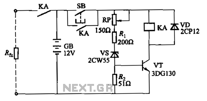
Deep discharge of a battery can lead to plate curing, which shortens the battery's lifespan. To prevent this, a discharge protection device can be implemented. The circuit diagram illustrates this mechanism. When the battery voltage falls to a predetermined...
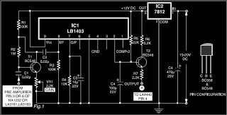
This is a circuit diagram for automatic muting in audio systems utilizing the IC LB1403. The output from a pre-amplifier, such as the LA3160, LA3161, or HA1032, is connected to the base of the amplifier transistor BC548 (T1). A...
Warning: include(partials/cookie-banner.php): Failed to open stream: Permission denied in /var/www/html/nextgr/view-circuit.php on line 713
Warning: include(): Failed opening 'partials/cookie-banner.php' for inclusion (include_path='.:/usr/share/php') in /var/www/html/nextgr/view-circuit.php on line 713