
25 Watt Audio Amplifier Circuit
The amplifier circuit operates with a primary voltage of 220V and a secondary output of 25 + 25V from a 120VA mains transformer (T1). The design incorporates a bridge rectifier (D1) rated for 200V and 8A, ensuring efficient conversion from AC to DC. The circuit features several fuses (F2) rated at 3.15A for protection against overcurrent conditions.
For optimal performance, transistors Q6 and Q7 require a small U-shaped heatsink, while Q8 and Q9 must be mounted on a heatsink to dissipate heat effectively. The quiescent current is adjustable via resistor R11, which should be set to 100mA, measured using an ammeter connected in series with the drain of Q8, ensuring no input signal during adjustment.
The grounding scheme is crucial for reducing noise; it is recommended to connect the ground sides of R1, R4, R9, and capacitors C3 to C8 at a single point. Capacitor C11 should be connected to the output ground, while the input and output grounds should be separately connected to the power supply ground.
This amplifier design stands out for its simplicity and performance, making it an ideal choice for audio enthusiasts seeking a cost-effective solution without compromising on sound quality.This is a 25 Watt basic power amp that was designed to be (relatively) easy to build at a reasonable cost. It has better performance than the standard STK module amps that are used in practically every mass market stereo receiver manufactured today.
When I originally built this thing, it was because I needed a 25 Watt PC amp and did not want to sp end any money. So I designed around parts I had in the shop. R1 = 47K R2 = 4K7 R3 = 1K5 R4 = 47K R5 = 390R R6 = 470R R7 = 33K R8 = 150K R9 = 15K R10 = 27R R11 = 500R-1/2W R12 = 10R R13 = 10R R14 = 220R R15 = 220R R16 = 10R R17 = 8. 2R-2W R18 = 22R-4W(wirewound) C1 = 470nF-63V C2 = 330pF-63V C3 = 470 µF-63V C4 = 100nF-63V C5 = 470 µF-63V C6 = 100nF-63V C7 = 100 µF-25V C8 = 100nF-63V C9 = 10pF-63V C10 = 1 µF-63V C11 = 100nF-63V Q1 = BC560C Q2 = BC560C Q3 = BC560C Q4 = BC560C Q5 = BC560C Q6 = BD140 Q7 = BD139 Q8 = IRF530 Q9 = IRF9530 R1 = 3K3-1/2W C1 = 10nF-1000V C2 = 4700 µF-50V C3 = 4700 µF-50V C4 = 100nF-63V C5 = 100nF-63V D1 = 200V 8A Diode bridge D2 = 5mm.
Red LED F2 = 3. 15A Fuses with sockets F2 = 3. 15A Fuses with sockets T1 = 220V Primary, 25 + 25V Secondary 120VA Mains transformer PL1 = Male Mains plug SW1 = SPST Mains switch * Can be directly connected to CD players, tuners and tape recorders. Simply add a 10K Log potentiometer (dual gang for stereo) and a switch to cope with the various sources you need.
* Q6 & Q7 must have a small U-shaped heatsink. * Q8 & Q9 must be mounted on heatsink. * Adjust R11 to set quiescent current at 100mA (best measured with an Avo-meter connected in series to Q8 Drain) with no input signal. * A correct grounding is very important to eliminate hum and ground loops. Connect to the same point the ground sides of R1, R4, R9, C3 to C8. Connect C11 to output ground. Then connect separately the input and output grounds to power supply ground. * An earlier prototype of this amplifier was recently inspected and tested again after 15 years of use.
Results, comments and pictures are shown here. 🔗 External reference
Related Circuits
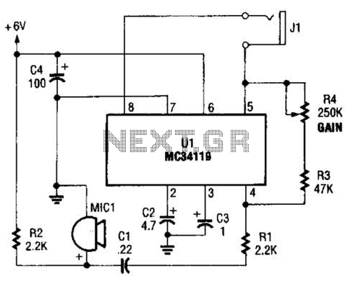
The first amplifier circuit is a bird phone. In this circuit, the electret microphone (MIC1) is mounted in the neck of a large plastic funnel. The amplifier, built around an MC34119, is then placed outside of the funnel with...
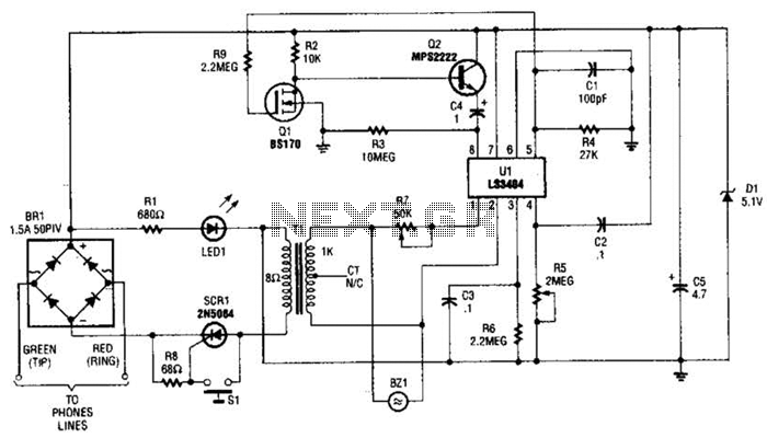
The LS3404 melody chip is activated when the hold switch (SI) is pressed, causing SCR1 to conduct and maintain the telephone line through Tl, Rl, and LED1. The voltage across Rl and LED1 is utilized to power the melody...
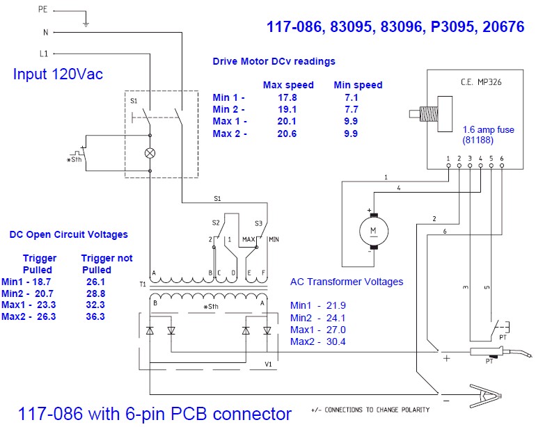
The wire speed DC motor consistently receives approximately 20 volts, irrespective of the switch position on the nozzle handle. The switch has been tested with an ohmmeter and functions properly. Even after disconnecting the switch from the circuit board,...
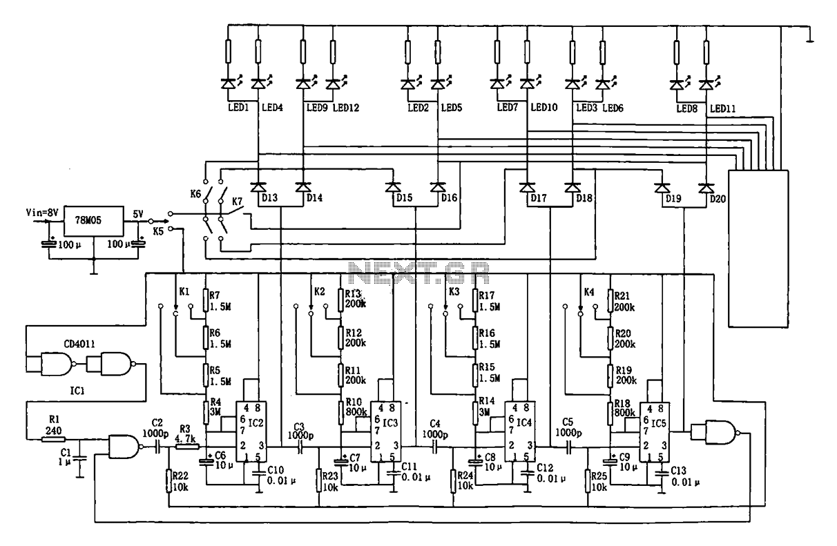
This document describes an automatic traffic intersection light control circuit. It features four monostable delay circuits, which consist of four 555 timer integrated circuits (IC2 to IC5) and several RC components interconnected. An 8V input voltage is regulated through...
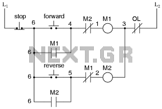
This is the power diagram for motor forward and reverse operation. To change the motor direction, one polarity must be altered, for example, changing R to S. For detailed information, please refer to the following. The described power diagram illustrates...
Stereo tube amplifier circuit built with 5 power tubes: 6SQ7-GT, 6V6-GT, and 5Y3-GT. This circuit generates up to 4 watts of audio output per channel. The stereo tube amplifier circuit utilizes a combination of five power tubes, specifically the 6SQ7-GT,...
Warning: include(partials/cookie-banner.php): Failed to open stream: Permission denied in /var/www/html/nextgr/view-circuit.php on line 713
Warning: include(): Failed opening 'partials/cookie-banner.php' for inclusion (include_path='.:/usr/share/php') in /var/www/html/nextgr/view-circuit.php on line 713