
Telephone relay circuit
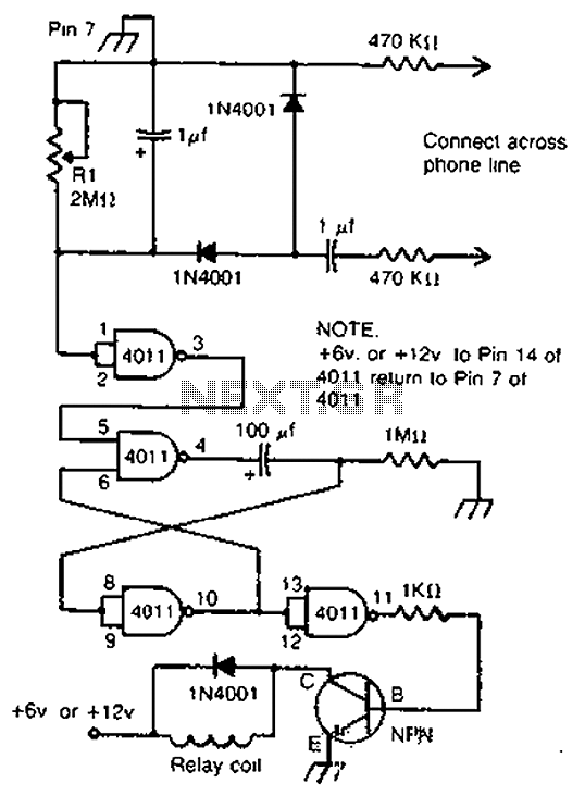
The telephone ringing circuit is designed to detect the ringing signal from a telephone line and use this signal to control a relay. The relay acts as a switch that can activate other devices, providing an alert or notification when a call is incoming. The circuit typically includes a resistor-capacitor (RC) delay network that introduces a time delay before the relay is energized. This delay allows for a smooth transition and prevents false triggering due to transient signals.
In the schematic, the telephone line is connected to a detection circuit that identifies the ringing voltage, which is typically around 90 volts AC at 20 Hz. This detection circuit may consist of a transformer to step down the voltage and rectify it to a suitable level for triggering the relay. The relay contacts are rated to handle the load of the connected devices, which can include various audible or visual alert systems such as bells, sirens, buzzers, or lights.
Furthermore, the circuit may incorporate additional components such as diodes for flyback protection, ensuring that voltage spikes generated when the relay coil is de-energized do not damage the circuit. An LED indicator can also be included to provide a visual indication of the circuit's operation, illuminating when the relay is active.
Overall, this telephone ringing circuit is a versatile solution for alerting individuals of incoming calls, enhancing communication in various environments, including homes, offices, and industrial settings. Proper design and component selection are crucial for ensuring reliable performance and longevity of the circuit. By cross-connect telephone ringing circuit, when the phone rang, the circuit closes the relay. It uses the delay in contact, thus to drive any bells, sirens, buzzers or lights.
Related Circuits
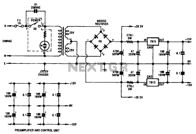
A dual audio amplifier that delivers 50 W per channel is illustrated in the schematic. It features a preamplifier and tone controls, as well as a headphone amplifier. The circuit also shows a power supply providing 38.5 V and...
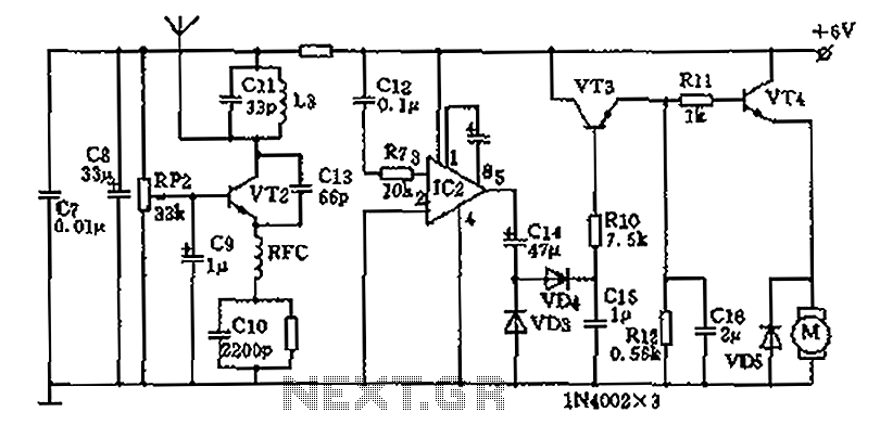
The homemade wireless remote control circuit diagram illustrates a motor remote control transmitter circuit. The circuit utilizes a 555 timer along with resistors R1, R2, RP1, diodes VD1, VD2, and capacitor C1 to create a variable duty cycle astable...
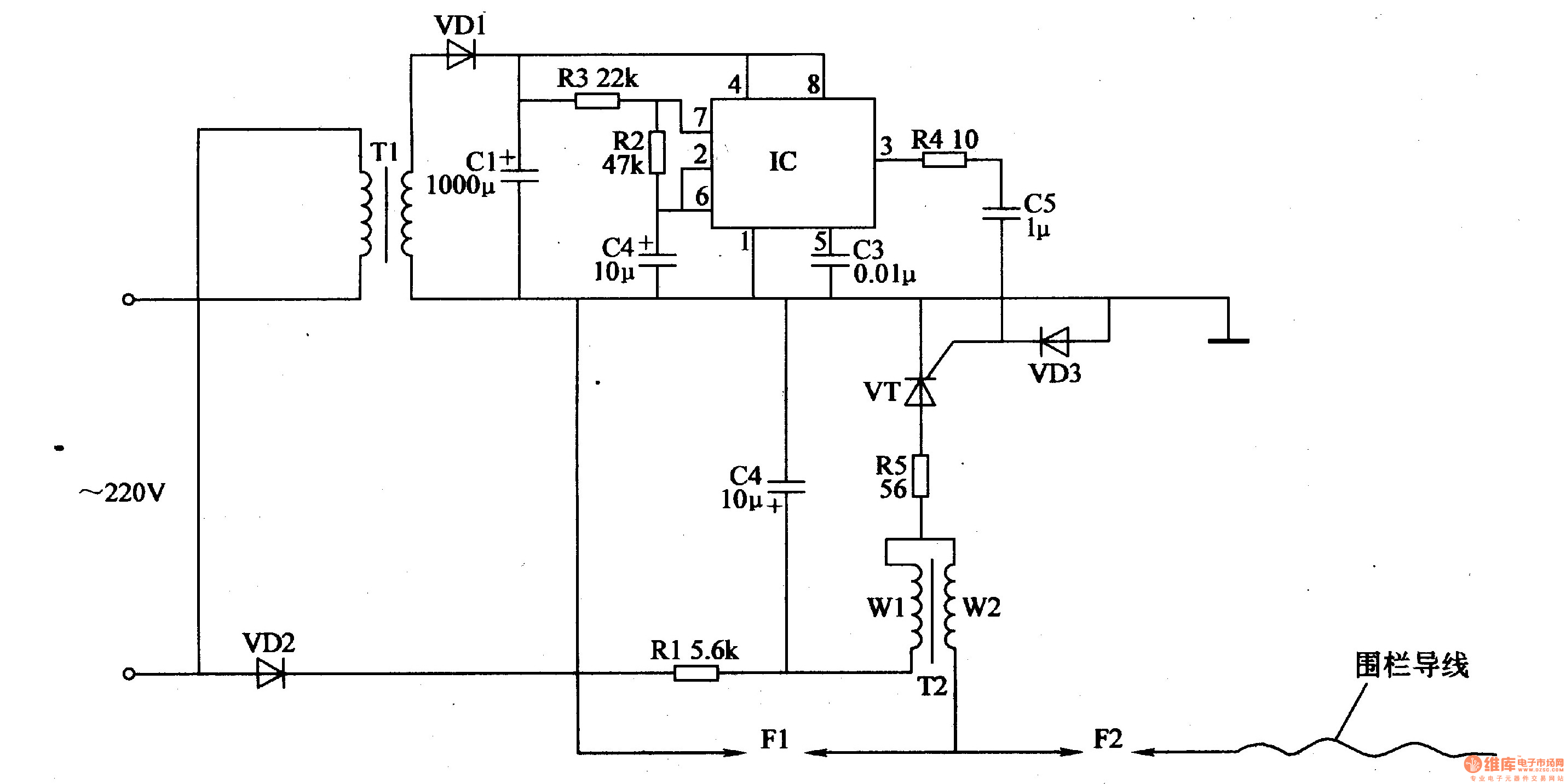
The electric fence control circuit consists of a power supply circuit, a pulse generator, and a high-voltage circuit, as illustrated in Figure 4-27. The power supply circuit includes a power transformer (T1), rectifier diodes (VD1, VD2), filter capacitors (C1,...
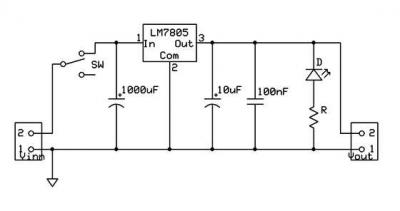
A micro power supply unit (PSU) is designed to power a breadboard with a voltage output of 5 volts. It can be connected to a 9V battery, a 12V source, or any other direct current (DC) power supply ranging...
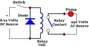
A relay is an isolated switch, with no direct connection between the switching device and the load. Relays are commonly used to control high-voltage devices, protecting sensitive low-voltage components from damage. Various types of relays exist, but electromechanical relays...
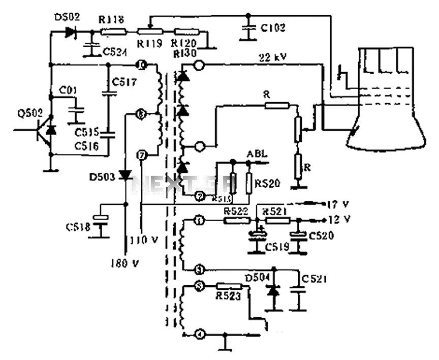
The circuit diagram of the Swallow CS37-2 type color TV illustrates the feeding tube configuration. The filament voltage is supplied by the line flyback transformer, with a current-limiting resistor R523. The accelerating voltage is managed by D502, which rectifies...
Warning: include(partials/cookie-banner.php): Failed to open stream: Permission denied in /var/www/html/nextgr/view-circuit.php on line 713
Warning: include(): Failed opening 'partials/cookie-banner.php' for inclusion (include_path='.:/usr/share/php') in /var/www/html/nextgr/view-circuit.php on line 713