
Homemade wireless remote control circuit diagram
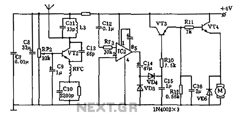
For circuit debugging, it is essential to focus on the transmitter carrier frequency oscillator. Temporarily install the high-frequency choke coil B and RFC while shorting C4 to ground. Adjust R3 to ensure the collector current of VT1 reaches 12mA. After installing crystal B, the current should rise to about 15mA; adjust the core of L1 carefully until the circuit starts, then remove the short from C4. The super-regenerative detector can be debugged using high-impedance headphones (800 series) connected with a 10uF capacitor across the emitter and collector of VT2. Fine-tune the coil L3 and its core with potentiometer RP2 until a noticeable rustling sound is heard through the headset. Bring the transmitter antenna close to the receiver and turn on the control switch S, then fine-tune the transmitter and receiver coil core until the headset clearly hears the frequency sound stop. After separating the two devices, further fine-tuning may be necessary. The remaining parts of the circuit generally do not require additional debugging and can be installed as is. As shown in FIG homemade wireless remote control circuit diagram; A motor remote road works Wireless remote control transmitter circuit As shown for the remote control transmit ter. Manifold 555 and R1, R2, RP1, VD1, VD2 and C1 form a wide range of variable duty cycle astable oscillator. Oscillation frequency parameter is shown around 50Hz, by adjusting the resistance RP1, vary the duty cycle of up to 1% to 99%, by the pin output 50Hz square wave signal.
VT1 and external components, crystal frequency stabilization capacitance three-point oscillator, the resonant frequency of the quartz crystal selection 27.145MHz. The quartz crystal frequency stabilization circuit, so reliable. VT1 modulated square wave signal generated by the oscillation circuit 555 via the high-frequency carrier feet from the antenna out.
Second, the choice of components Available 10K L1 type skeleton in the week, with µ0.15 high strength enameled wire around 9 turns, L2 with the same model in the outer wire 3 turns of L1, without shield, but need screwed core. L3 with L1 production. B with JAl2 other metal shell resonator frequency between 27-29.8MHz. VT1, VT2, VT3 are made 3DG130D type NPN transistor, 100. VT4 selection 3DD15D-power tube. RFC by 18uH inductors color code. IC1 model for NE555. IC2 model for the LM386. Unless otherwise specified capacitance electrolytic capacitors are used outside the high-frequency ceramic capacitors CC1.
Resistors are made of 1/8w carbon film resistors. Third, debugging circuit To emphasize the transmitter carrier frequency oscillator, high-frequency choke coil B crystal and RFC temporarily installed, make C4 a short to ground. Adjust R3 resistance, so that VT1 collector current of 12mA, then install the crystal B, this time the current will increase to about 15mA, or should be carefully adjusted core L1 until the start-up circuit, remove C4 short route.
Super-regenerative detector debugging method is to use a high-impedance headphones 800 series with a 10uF capacitor connected across the emitter and collector VT2, with no sense of screwdriver potentiometer RP2 fine tuning coil L3 and core, until the headset in obviously resounding rustling sound. Next to the transmitter antenna near the receiver, turn pass control switch S, to fine-tune the transmitter and the receiver coil core, until the headset can be heard clearly frequency sound stops, then pull away from the two planes, and then further fine-tuning.
Rest of the circuit without debugging, you can work generally installed after.
Related Circuits

This relay driver enhances the input impedance using a standard BC547 NPN transistor (or its equivalent). It is a widely used driver capable of operating various relays, including reed relays. Transistors Q1 and Q2 function as a simple common-emitter...
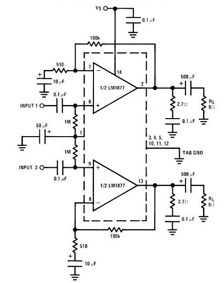
The LA4440 is a dual-channel audio power amplifier integrated circuit (IC) designed for stereo and bridge amplifier applications. In dual mode, it provides significant audio amplification for various audio systems. The LA4440 audio power amplifier is engineered to deliver high-quality...

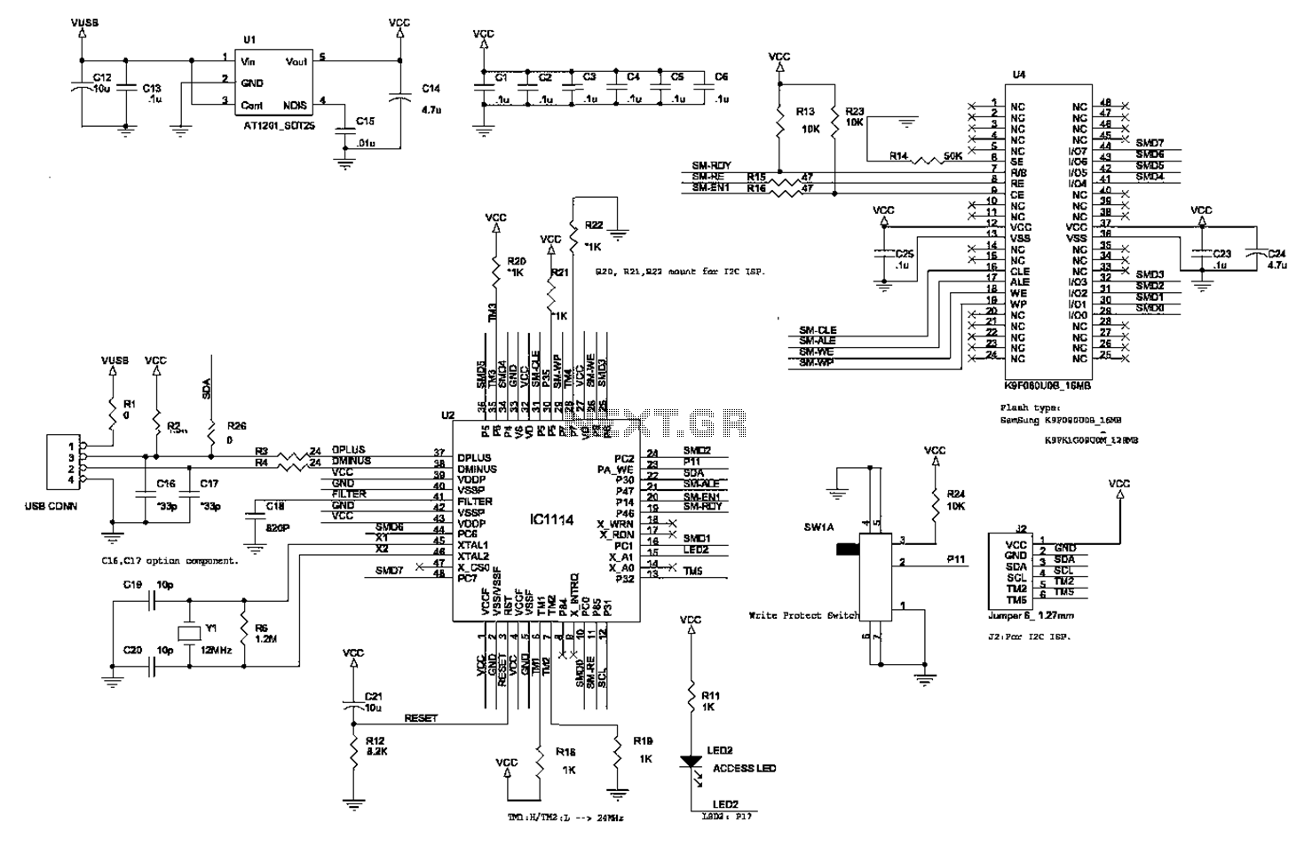
If the control circuit of this motor driver is based on a microcontroller or digital component, it is advisable to implement a buffer for each port that controls the stepper motor driver. This precaution helps prevent overloading the microcontroller...
Crystal 80mW FM transmitter circuit diagram of the production The Crystal 80mW FM transmitter circuit is designed to generate frequency modulated (FM) signals suitable for short-range audio transmission. This circuit primarily consists of a crystal oscillator, which serves as...
Powered by a solar panel, the circuit provides a 5V pure regulated DC voltage. It consists of an oscillator transistor and a regulator transistor. The solar panel charges the battery when sunlight is sufficient to generate a voltage above...
This circuit can be used for detecting infrared light; for example, it is utilized for detecting infrared band light signals in a spectrophotometer. The amplifier output voltage Vo is given by the formula Vo = Is·Rd·Rf/Ri, where Is is...
Warning: include(partials/cookie-banner.php): Failed to open stream: Permission denied in /var/www/html/nextgr/view-circuit.php on line 713
Warning: include(): Failed opening 'partials/cookie-banner.php' for inclusion (include_path='.:/usr/share/php') in /var/www/html/nextgr/view-circuit.php on line 713