
temp sensor circuit and code

The circuit design features the LM135 temperature sensor, which is a precision temperature sensor with an output voltage that is linearly proportional to the temperature in degrees Kelvin. The sensor operates by generating a reference voltage, which can be utilized to accurately measure temperature changes.
The foot-long cord serves as an extension, allowing the sensor to be placed in an environment where accurate temperature readings are essential, while the main electronic circuitry is protected within the payload housing. This separation not only ensures the safety of sensitive components but also enhances the accuracy of temperature measurements by reducing the influence of heat generated by the electronics on the sensor.
The plug connection is designed for ease of assembly and disassembly, facilitating maintenance and replacement of the sensor if necessary. The circuit may include additional components such as resistors for biasing, capacitors for noise filtering, and possibly an operational amplifier to condition the signal from the LM135 before further processing or transmission.
Overall, the schematic provides a clear and functional design for integrating a temperature sensor into a larger system, emphasizing both the practical application and the technical specifications required for optimal performance.Here is the schematic diagram of the temperature sensor we will be launching. The Zener diode is actually the LM135 sensor which is attached to the end of a foot-long cord and connects to the circuit through a plug. That way the sensor can be outside the payload housing while the electronics will be snug.. 🔗 External reference
Related Circuits
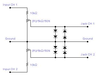
For simple electronic circuits, it may be sufficient to gain qualitative insights on dedicated electrical signals. This interface circuitry allows the line-in input of a standard PC sound card to be utilized as a 2-channel oscilloscope. Although this setup...

This is a VU meter analog circuit. The circuit is connected to the line terminals of the amplifier. The VU meter operates simply, with T1 and T2 indicating signal increases. The VU meter circuit is designed to visually represent audio...
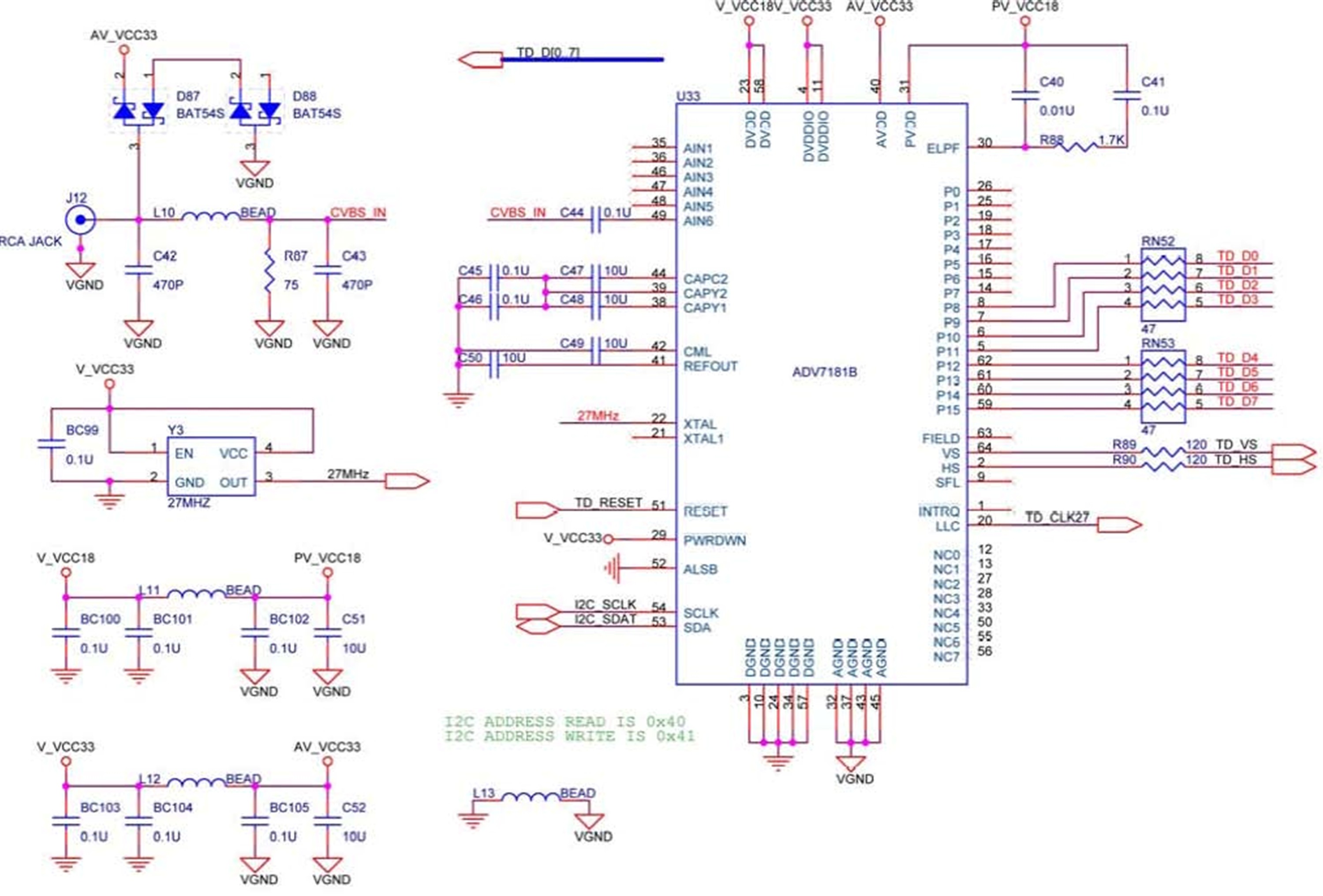
The DE2 board features an Analog Devices ADV7181 TV decoder chip. The ADV7181 is an integrated video decoder that automatically detects and converts standard analog baseband television signals (NTSC, PAL, and SECAM) into 4:2:2 component video data, which is...
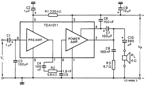
The following schematic illustrates the design of a 4 Watt Amplifier Circuit Diagram intended for portable radio applications, utilizing the TDA1011 integrated circuit from Philips Semiconductor. The 4 Watt Amplifier Circuit is designed to provide audio amplification in portable radio...
This is a low-cost 150-watt amplifier circuit with a diagram and schematic design utilizing two Darlington power transistors, TIP142 and TIP147. The 150-watt amplifier circuit is designed to provide high power output while maintaining cost efficiency, making it suitable for...
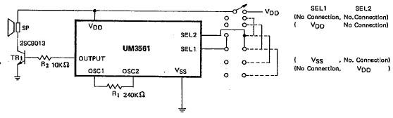
This siren alarm circuit diagram utilizes the specialized integrated circuit (IC) UM3561, which is a low-power CMOS large-scale integration (LSI) device specifically designed for such applications. The UM3561 incorporates all necessary components, including an oscillator, selector circuits, and programmed...
Warning: include(partials/cookie-banner.php): Failed to open stream: Permission denied in /var/www/html/nextgr/view-circuit.php on line 713
Warning: include(): Failed opening 'partials/cookie-banner.php' for inclusion (include_path='.:/usr/share/php') in /var/www/html/nextgr/view-circuit.php on line 713