
Temperature Controller For PC PCB
The temperature controller circuit is designed to maintain optimal operating conditions for personal computers by monitoring and regulating internal temperatures. The LM35 temperature sensor provides a precise voltage output proportional to the temperature, allowing for accurate monitoring. The CA3140 comparator compares the output voltage from the LM35 with a reference voltage set by the VR1 potentiometer. This adjustable reference allows for customization of the cutoff temperature according to user requirements.
When the temperature remains below the set threshold, the comparator outputs a high signal, keeping the triac in the conducting state, which allows current to flow to the PC. This ensures that the computer remains operational during normal conditions. However, once the temperature exceeds 55 degrees Celsius, the comparator's output drops to a low state, which turns off the triac. This action interrupts the power supply to the PC, effectively shutting it down and preventing potential damage from overheating.
The resistors R1 and R2 serve to stabilize the output voltage from the rectifier circuit, ensuring reliable operation of the temperature controller. The ZD1 component, a zener diode rated at 9V and 0.5W, provides additional voltage regulation, maintaining consistent performance across varying input conditions.
This temperature control circuit is particularly beneficial for high-performance PCs that generate significant heat during operation, as it helps to prolong the lifespan of critical components by preventing thermal stress. By integrating this simple yet effective temperature controller, users can safeguard their systems from the adverse effects of overheating, ensuring stable and reliable performance.Our computer may often heated up due to long use or the hot climate, temperature controllers are necessary. You need to do a temperature measurement to ensure that the computer is work within the allowed range.
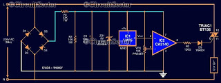
To reduce pc temperature, here is circuit diagram of a simple temperature controller for your personal computer (PC) based on a temperatur e sensor LM35 and a comparator CA3140. The circuit turns off the PC when the temperature of the computer increases beyond a particular, optimum temperature value. This avoids overheating of some integrated chips (IC) that may not be able to dissipate heat fast enough.
For this pc temperature controller, the cut off temperature is assumed to be 55 degree Celsius. The circuit contains a temperature sensor LM35 and comparator. ( The threshold value of 55 can be adjusted using VR1 potentiometer actually varies the comparator reference voltage). The R1, R2 and ZD1(9V, 0. 5W) used for stabilizing the output of the rectifier. In normal temperature, the comparator produces an error voltage which triggers the triac that give supply to PC (load).
Whenever the PC temperature go beyond the threshold value, the comparator output become low, causes to shut down the triac hence the PC. 🔗 External reference
Related Circuits
The circuit depicted in the figure integrates a temperature detection system, a temperature-voltage switch, and a voltage-frequency switch to enable remote temperature monitoring. This circuit is connected to a wireless transmission circuit, creating a remote control temperature detection system....

The core component of this digital volume controller (DVC) circuit is the IC2 4067, which is a 16-channel analog multiplexer. A 1kΩ resistor is connected between each input and output, allowing the multiplexer to function similarly to a potentiometer....
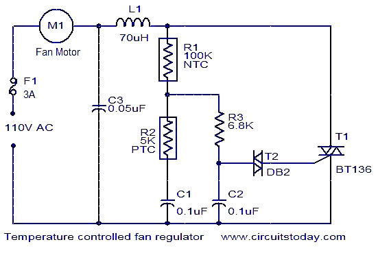
This fan regulator circuit automatically controls the speed of a fan based on temperature. It utilizes two thermistors (R1 and R2) for temperature sensing. The operation is similar to previously published designs, with thermistors replacing the potentiometer. As the...
The following circuit illustrates the AT90LS2323 Microcontroller Circuit Diagram. Features include a voltage range of 2.7 to 6 volts, and compatibility with all 2323 chips. Components are included. The AT90LS2323 microcontroller circuit is designed to operate within a voltage range...

Tom Au-Yeung and Wilson Tang from Maxim Integrated Products describe a method to create a wireless temperature monitoring system using two integrated circuits (ICs). This system can be designed utilizing a local temperature sensor along with an amplitude-shift-keying (ASK)...
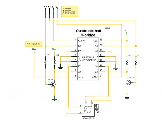
A stepper motor controller based on schematics available on the Arduino website. Initially, a two-pin configuration was attempted for a bipolar stepper motor, but it did not function as expected, especially with the library provided on the site. The...
Warning: include(partials/cookie-banner.php): Failed to open stream: Permission denied in /var/www/html/nextgr/view-circuit.php on line 713
Warning: include(): Failed opening 'partials/cookie-banner.php' for inclusion (include_path='.:/usr/share/php') in /var/www/html/nextgr/view-circuit.php on line 713