
Digital volume controller DVC circuit using IC 4067

The digital volume controller utilizes the 4067 multiplexer to manage audio signal levels effectively. The 16-channel configuration of the IC enables it to select one of the multiple input signals based on the binary control signals applied to its select pins. Each channel is connected to a 1kΩ resistor, which serves to limit current and prevent signal distortion, thereby allowing the multiplexer to simulate the behavior of a traditional potentiometer.
In this configuration, the total resistance of 15kΩ is achieved by the series connection of the 1kΩ resistors across the 16 channels. This design ensures that each selected channel maintains a minimum resistance, contributing to a smoother audio transition and reducing the potential for clicks or pops during volume adjustments.
The control signals for the multiplexer are typically generated by a microcontroller or a digital signal processor (DSP), which can be programmed to adjust the volume levels dynamically based on user input or audio processing algorithms. The output of the multiplexer can be connected to an audio amplifier or directly to speakers, depending on the application requirements.
In summary, this digital volume controller circuit effectively combines the functionality of an analog multiplexer with the characteristics of a potentiometer, providing a versatile solution for volume control in audio applications. The use of the 4067 IC allows for multiple input channels, while the resistor network ensures consistent performance and signal integrity.The heart of this digital volume controller DVC circuit is IC2 4067 , 16-channel analog multiplexer. Because the 1k has been connected between every input and output, the multiplexer can act like a potentiometer. The total resistance is 15k.. 🔗 External reference
Related Circuits
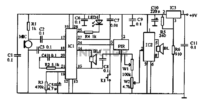
Doppler effect sensor N1 (RD627), operational amplifier N2 (LM358), and a special integrated circuit for imitating dog barking (N3, KD5608) are utilized along with other components. When there is no activity detected in the monitoring area by N1, the...
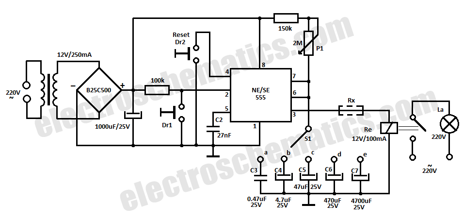
This time delay relay circuit is constructed using the NE/SE555 integrated circuit, manufactured by Intersil, which features a precision timer. The circuit exhibits stability against temperature variations. The NE/SE555 integrated circuit is a versatile timer used in various applications, including...
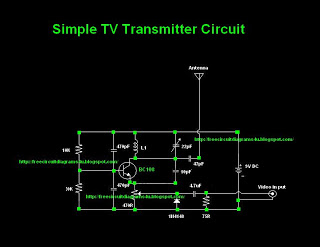
Many individuals inquire about TV transmitters. This document provides a useful circuit diagram that enables signal transmission over distances of 75 to 100 meters. The circuit diagram is not original but was provided by a colleague. Contributions of circuit...
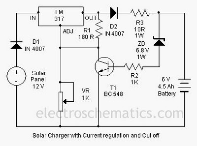
A solar charger circuit is designed to charge lead-acid batteries or nickel-cadmium (Ni-Cd) batteries using solar power. This circuit captures solar energy to charge a 6-volt, 4.5 Ah battery for various applications. It features voltage and current regulation along...
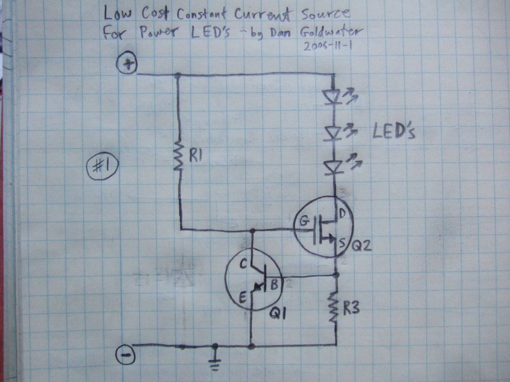
Here is a simple and inexpensive ($1) LED driver circuit. The circuit functions as a constant current source, ensuring that the LED maintains consistent brightness. The LED driver circuit is designed to provide a stable current to the LED, which...
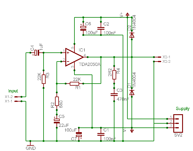
A careful examination of the amplifier photos reveals that the heatsink on the HY60 near-clone built using the TDA2050A is slightly shorter than that of the original HY60s. This unit is positioned at the rear of the amplifier, creating...
Warning: include(partials/cookie-banner.php): Failed to open stream: Permission denied in /var/www/html/nextgr/view-circuit.php on line 713
Warning: include(): Failed opening 'partials/cookie-banner.php' for inclusion (include_path='.:/usr/share/php') in /var/www/html/nextgr/view-circuit.php on line 713