
Temperature Controller with U217B
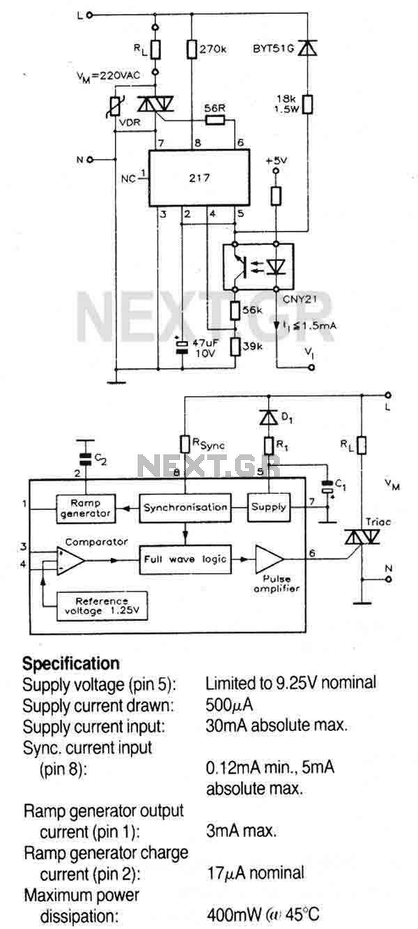
This triac controller circuit is designed to effectively manage resistive loads, utilizing a zero-crossing detection method to minimize electrical noise and reduce the risk of arcing in the switching device. The circuit is powered directly from the AC mains, with the input voltage being rectified by a diode. The dropper resistor serves to limit the current flowing into the circuit, ensuring safe operation.
The integrated circuit (IC) within the controller features an internal voltage regulator that stabilizes the supply voltage to 9.25V, which is critical for maintaining consistent performance of the control logic and timing functions. The zero-crossing technique is implemented to prevent the triac from switching on or off at any point other than the zero voltage crossing of the AC waveform, thus reducing electromagnetic interference (EMI) and improving the longevity of the connected load.
A timing capacitor is employed to determine the duration of the ramp signal, which is crucial for controlling the phase angle at which the triac is triggered. The ramp generator produces a symmetrical pulse that is synchronized with the AC supply voltage, ensuring that the timing of the triac activation is precisely coordinated with the mains frequency. The synchronization is achieved through a dedicated pin (pin 8) connected to the AC waveform via the dropper resistor (RSync), allowing the full-wave logic block to operate effectively.
The full-wave logic block plays a vital role in the circuit, ensuring that the triac is only activated during the appropriate half-cycles of the AC waveform. This functionality not only enhances the efficiency of the load control but also contributes to the overall safety and reliability of the system. With these design considerations, the triac controller provides a robust solution for switching resistive loads in various applications, from household appliances to industrial equipment.A triac controller for switching resistive loads directly from the mains supply using the zero crossing technique. The device is powered directly from the mains via a diode and dropper resistor, and the IC has its own regulator to limit its supply to 9.25V.
To ensure that no switching occurs outside of the zero crossing point, full wave logic is employed to guarantee that complete mains cycles only are switched to the load. A ramp a freely selectable ramp duration (as determined by a timing capacitor),together with the full-wave logic block, synchronised to the AC supply at pin 8 via a dropper resistor (RSync). The ramp generator not only provides symmetrical trigger pulse c 🔗 External reference
Related Circuits
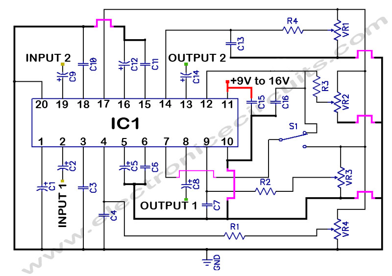
LM1036 Stereo Tone (Bass, Treble, Volume, Loudness, Balance) Controller Circuit. The LM1036 is a DC controlled tone (bass/treble), volume, and loudness controller designed for audio applications. The LM1036 circuit serves as an integrated solution for controlling various aspects of audio...
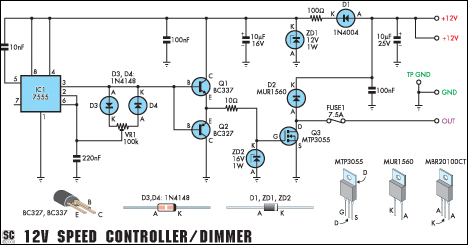
This circuit functions as a speed controller for a 12V motor with a continuous rating of up to 5A or as a dimmer for a 12V halogen or incandescent lamp rated up to 50W. It adjusts the power to...
The initial PIC program utilizing the C language demonstrates how to blink a single LED using a PIC microcontroller with a C program. This serves as an introduction to C programming for PIC microcontrollers. The circuit for blinking an LED...
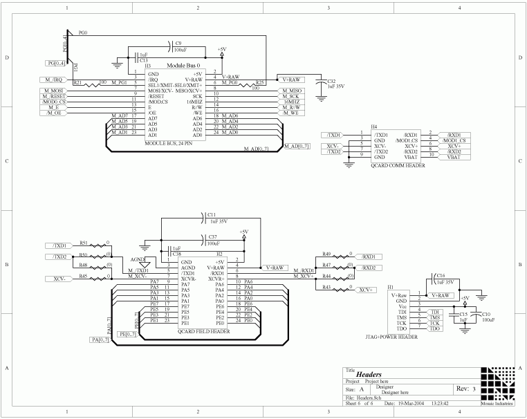
The QCard Controller Single Board Computer (SBC) features the Freescale 68HC11 microcontroller, along with RAM and Flash memory, digital input-output (I/O), and analog-to-digital (A/D) conversion capabilities. For comprehensive details regarding the QCard headers mentioned on this page, refer to...
A stepper motor controller is required to operate a stepper motor, as a stepper motor cannot function merely by connecting it to a power supply. A stepper motor controller is an essential component for the effective operation of stepper...
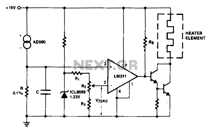
The AD590 generates a voltage that varies with temperature across resistor R, while capacitor C serves to filter out noise. To establish a zero-scale voltage, resistor R2 is adjusted. For the Celsius temperature scale, R should be set to...