
Temperature to Digital Converter Circuit
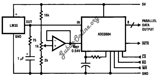
The circuit utilizes the LM35 temperature sensor to convert temperature readings into a digital format. The LM35 operates over a range of -55°C to +150°C, providing an output of 10 mV per degree Celsius. This characteristic allows for straightforward interfacing with analog-to-digital converters (ADCs) to facilitate digital signal processing.
In the schematic, the LM35 is connected to a microcontroller or an ADC via its output pin. The microcontroller can be programmed to read the voltage output from the LM35 and convert this analog voltage into a digital value through the ADC, which typically operates in a range of 0-5V or 0-3.3V. The reference voltage for the ADC must be set appropriately to ensure accurate temperature readings.
Additional components may include resistors for voltage division, capacitors for filtering noise, and possibly an operational amplifier to buffer the output signal from the LM35 if necessary. The design should also incorporate power supply decoupling capacitors close to the LM35 to stabilize its operation.
For applications requiring temperature monitoring, this circuit can be integrated into a larger system, such as a microcontroller-based temperature display or a data logging system. The output from the microcontroller can be utilized to trigger alarms or control heating systems based on the temperature readings. Overall, this design provides a reliable method for converting temperature measurements into a digital format suitable for various electronic applications.This is a design circuit for temperature to digital converter circuit that is based control by LM35 IC. This LM35 is precision integrated-circuit temperature sensors, whose output voltage is linearly proportional to the Celsius (Centigrade) temperatu ..
🔗 External reference
Related Circuits
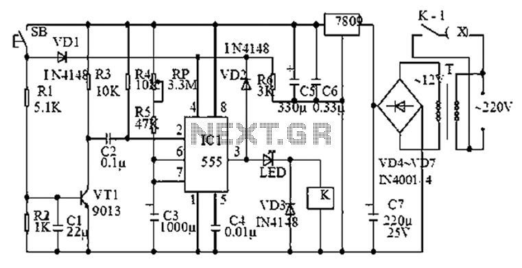
The 555 timer is commonly used in time-based circuit designs, particularly in monostable configurations. This setup is straightforward and requires only a few resistors and capacitors to achieve triggering. However, external interference can affect the operation of the circuit...
The ultrasonic sensor circuit comprises a transmitter and a receiver, which are essential for remote control applications. The circuit operates at sound frequencies above 20 kHz, typically between 40 kHz and 50 kHz, powered by a 9V battery. When...
This room light controller project automatically uses a microcontroller to manage a visitor counter, providing a reliable circuit for controlling the room lighting. The room light controller circuit integrates a microcontroller that processes inputs from a visitor counter. This setup...
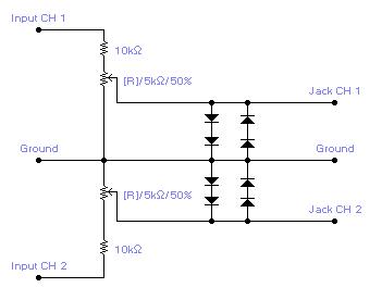
For simple electronic circuits, it may be sufficient to gain qualitative insights on dedicated electrical signals. This interface circuitry allows the line-in input of a standard PC sound card to be utilized as a 2-channel oscilloscope. Although this setup...
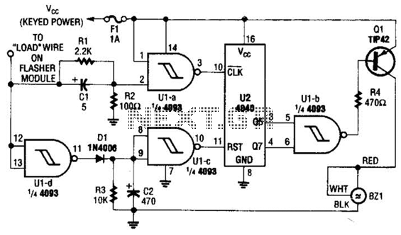
This circuit counts the flashes of turn signals. After approximately 70 flashes, a chime sounds to remind the driver to deactivate the turn signal. The period can be altered by using different taps on U2 if desired. BZ1 serves...
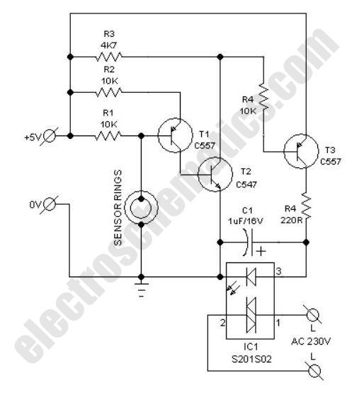
This compact water sensor alarm circuit emits a loud warning sound when a humidity sensor detects the presence of water. The circuit utilizes the low-power comparator LM1801 from National Semiconductor. A fixed reference voltage for the integrated circuit is...
Warning: include(partials/cookie-banner.php): Failed to open stream: Permission denied in /var/www/html/nextgr/view-circuit.php on line 713
Warning: include(): Failed opening 'partials/cookie-banner.php' for inclusion (include_path='.:/usr/share/php') in /var/www/html/nextgr/view-circuit.php on line 713