
Test Signal Generator
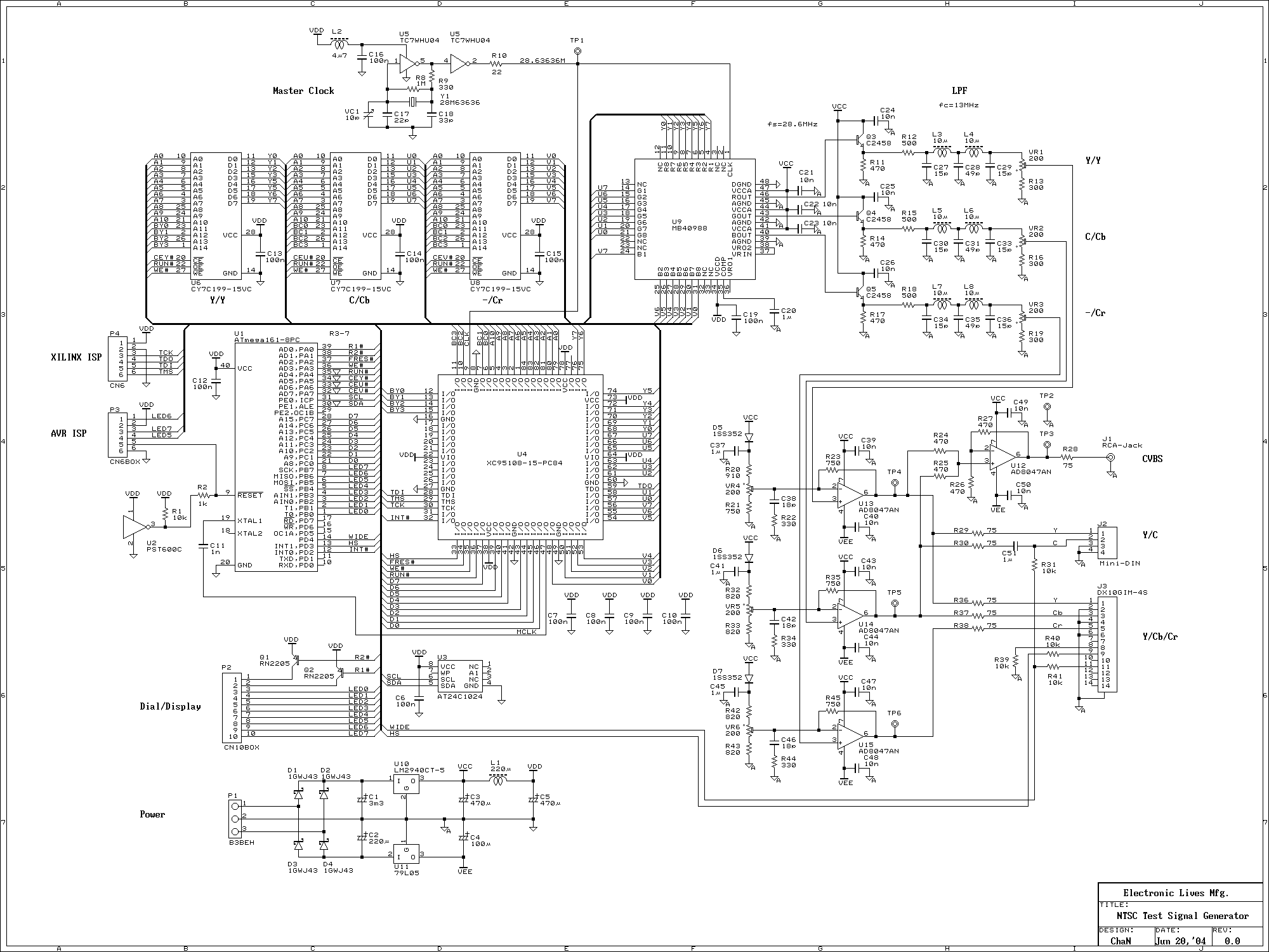
The signal generator described employs a three-channel Digital-to-Analog Converter (DAC) to produce both Composite Video Signal (CVBS) and S-Video (Y/C separated) outputs simultaneously. The architecture utilizes one channel of the DAC to generate the Y (luminance) component while the other two channels are utilized for the color components in the Y/CB/CR format. The design acknowledges the impending obsolescence of the NTSC television system, which may necessitate a shift to more modern video formats.
In the schematic, the DAC's three output channels are configured to interface with respective video processing circuits. The first channel outputs the Y component, which is essential for both CVBS and S-Video formats. The second channel is dedicated to the Cb (blue-difference chroma) component, while the third channel handles the Cr (red-difference chroma) component, enabling the generation of high-quality component video signals.
The design includes necessary filtering and buffering stages to ensure signal integrity and minimize distortion across the outputs. The CVBS output is derived from combining the Y, Cb, and Cr signals, while the S-Video output is achieved by separating the Y and C signals, allowing for improved video quality through reduced cross-talk between luminance and chrominance.
This dual-output capability enhances versatility, making the signal generator suitable for various applications, including testing and interfacing with both legacy NTSC systems and newer component video standards. The design reflects an awareness of the evolving landscape of video technology, ensuring compatibility with both current and future standards.This signal generator uses a three channel DAC to generate Composite video signal (CVBS) and S video signal (Y/C separated) at the same time, left one channel is not used in NTSC format. It is assigned for one of the color components of Y/CB/CR video format. This feature was not planned some years ago, but it has been added when started to draw the schematic this year, because NTSC television system might be obsoleted in the near future. The two different video format, component video and NTSC video, work in 🔗 External reference
Related Circuits
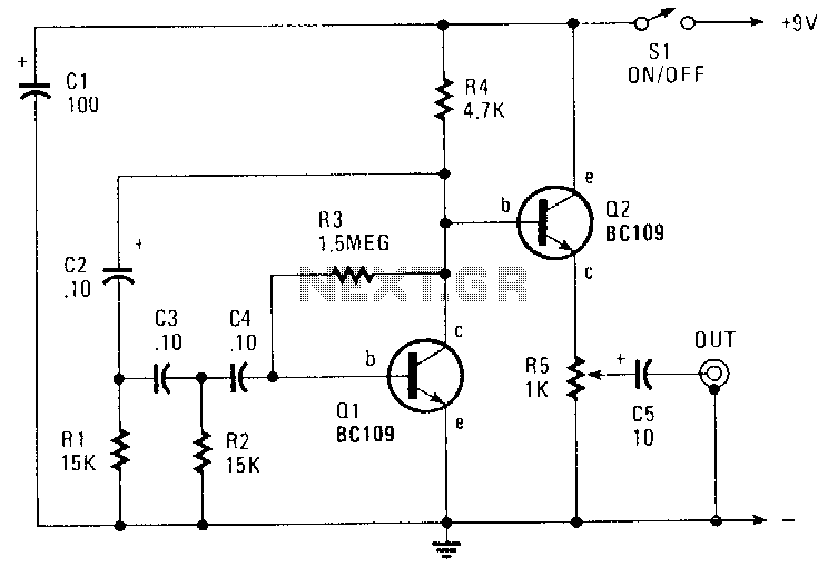
This circuit generates a sinusoidal output of approximately 8 V peak-to-peak, which can be adjusted down to zero, operating at a frequency of about 500 Hz. The signal is produced by a phase-shift oscillator. The described circuit utilizes a phase-shift...
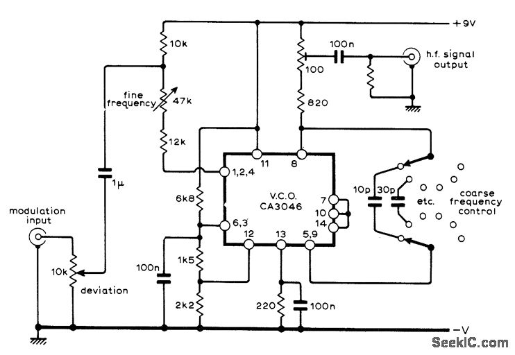
A sine-wave input can be applied to an RCA CA3046 transistor array configured as a voltage-controlled oscillator (VCO), which functions effectively as a low-distortion frequency modulation (FM) signal generator. When a sawtooth input is utilized, the same configuration operates...
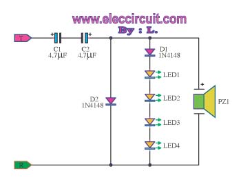
The circuit detects a ringing signal tone and provides both light and sound indicators. It is user-friendly and of good quality, and it does not require a power supply to operate, functioning solely to detect the ringing signal. The described...

The PACO C-25 differs from the Healthkit IT-22b in that it tests both regular and electrolytic capacitors and utilizes a 40 MHz oscillator to allow a rough measurement of capacitance through a bridge circuit. In vintage vacuum tube equipment,...
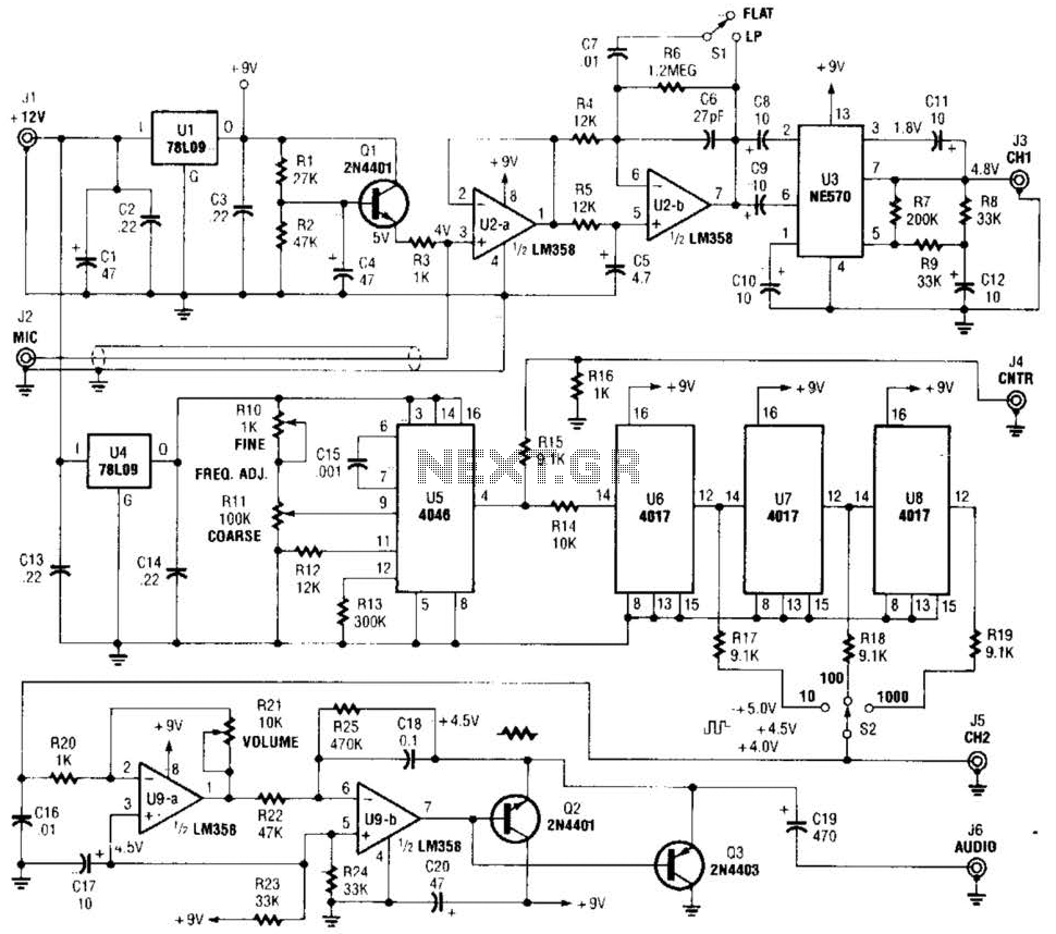
The precision audio frequency generator consists of several sub-circuits: an audio amplifier/filter circuit, an automatic level control, a variable voltage-controlled oscillator, a frequency divider circuit, an integrator, and an audio output amplifier. An electret microphone element is utilized to...
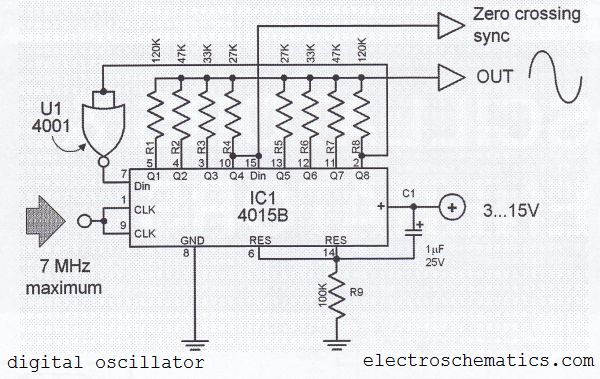
The digital sine wave generator (oscillator) circuit requires only a few components to produce signals with high amplitude constants and a wide range of variable frequencies. This circuit generates a sine wave signal, and by altering the values of...