
Digital Sine Wave Generator Circuit

The digital sine wave generator circuit is designed to produce a sine wave output efficiently by utilizing a minimal number of components. At its core, the circuit employs a CMOS integrated circuit, specifically the 4015B, which is a dual 4-stage static shift register. The configuration of the resistors R1 and R8 allows for the adjustment of the waveform characteristics, enabling the generation of alternative signal forms such as triangular or square waves, depending on the application requirements.
Upon powering the circuit, the reset mechanism implemented through the resistor-capacitor combination of R9 and C1 ensures that all outputs of the 4015B are initialized to a known state (logic 0). This is crucial for the reliable operation of the circuit, preventing undefined states that could lead to erratic behavior.
The external clock signal serves as the timing reference for the oscillator. The relationship between the clock frequency and the output sine wave frequency is established such that the sine wave output is one-eighth of the clock frequency. This division is achieved through the internal logic of the 4015B, which effectively creates a frequency divider circuit.
The design also takes into account the limitations of the CMOS technology used. With a maximum operational frequency of 7 MHz for the CMOS ICs, the sine wave generator can achieve a peak output frequency of 500 kHz. This makes the circuit suitable for various applications, including signal processing, waveform generation, and testing scenarios where sine wave signals are required.
In summary, the digital sine wave generator circuit is a versatile and efficient solution for generating sine wave signals with high amplitude and variable frequencies, leveraging the capabilities of a CMOS integrated circuit while ensuring stability and reliability through careful component selection and configuration.The digital sine wave generator (oscillator) circuit has the advantage that only few components are needed to generate signals with high amplitude constants and variable within a very wide range of frequencies. The circuit shown here generates a sinewave signal. Other signal forms can also be generated by changing the values of R1 R8. After the power supply is connected to the circuit, the combination R9/C1 generates a short reset-pulse and all outputs if the 4015B are set to logic 0. The oscillator is controlled by an external clock. The frequency of the sinewave is 1/8 of the clock frequency. The highest frequency of CMOS ICs is 7 MHz, therefore a sine wave signal of 500 kHz maximum can be generated.
🔗 External reference
Related Circuits
Sometimes when experimenting with different soundcards and MIDI interfaces it is useful to see if there is some data going in MIDI interface. This can be easily tested with this adapter, which converts the midi signals to visible light...
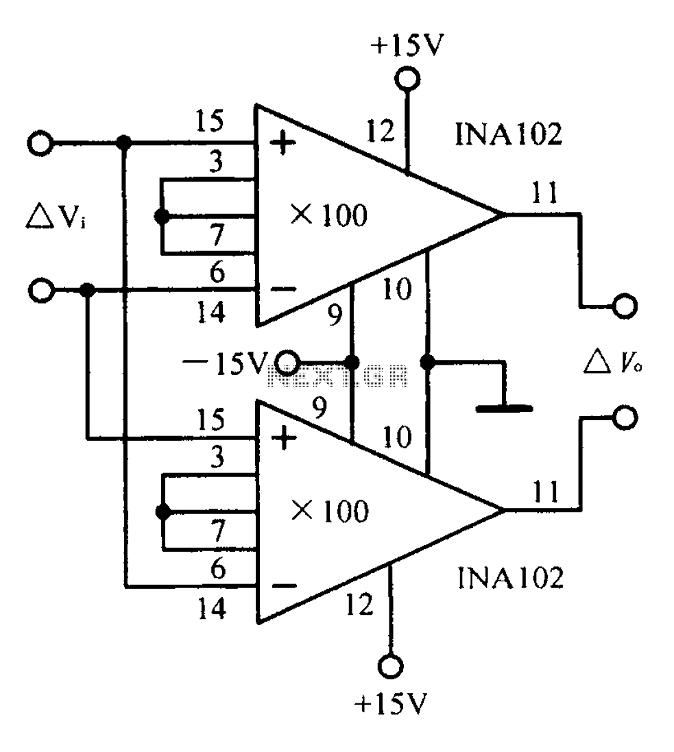
A differential input differential output amplifying circuit diagram. A differential input differential output (DIDO) amplifier is a type of operational amplifier configuration that is designed to amplify the difference between two input signals while rejecting any signals that are common...
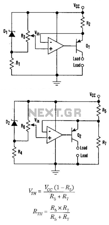
This setup can function as a cost-effective current source with an output accuracy of 1%. However, the voltage offset can activate the current source even when Vqq equals Vin. Modifying the configuration of Figure 1 can resolve the issue...
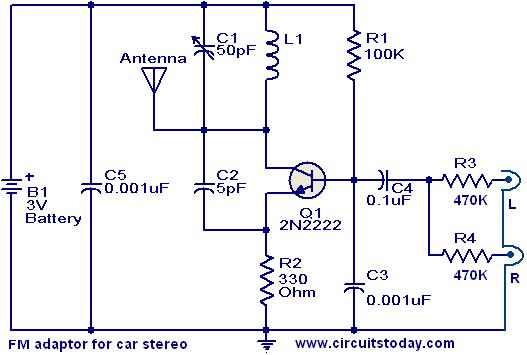
This compact FM adapter circuit, when connected to the audio output of a cassette player or iPod, enables the user to listen to their favorite music through a car stereo. It is particularly useful for vehicles that lack an...
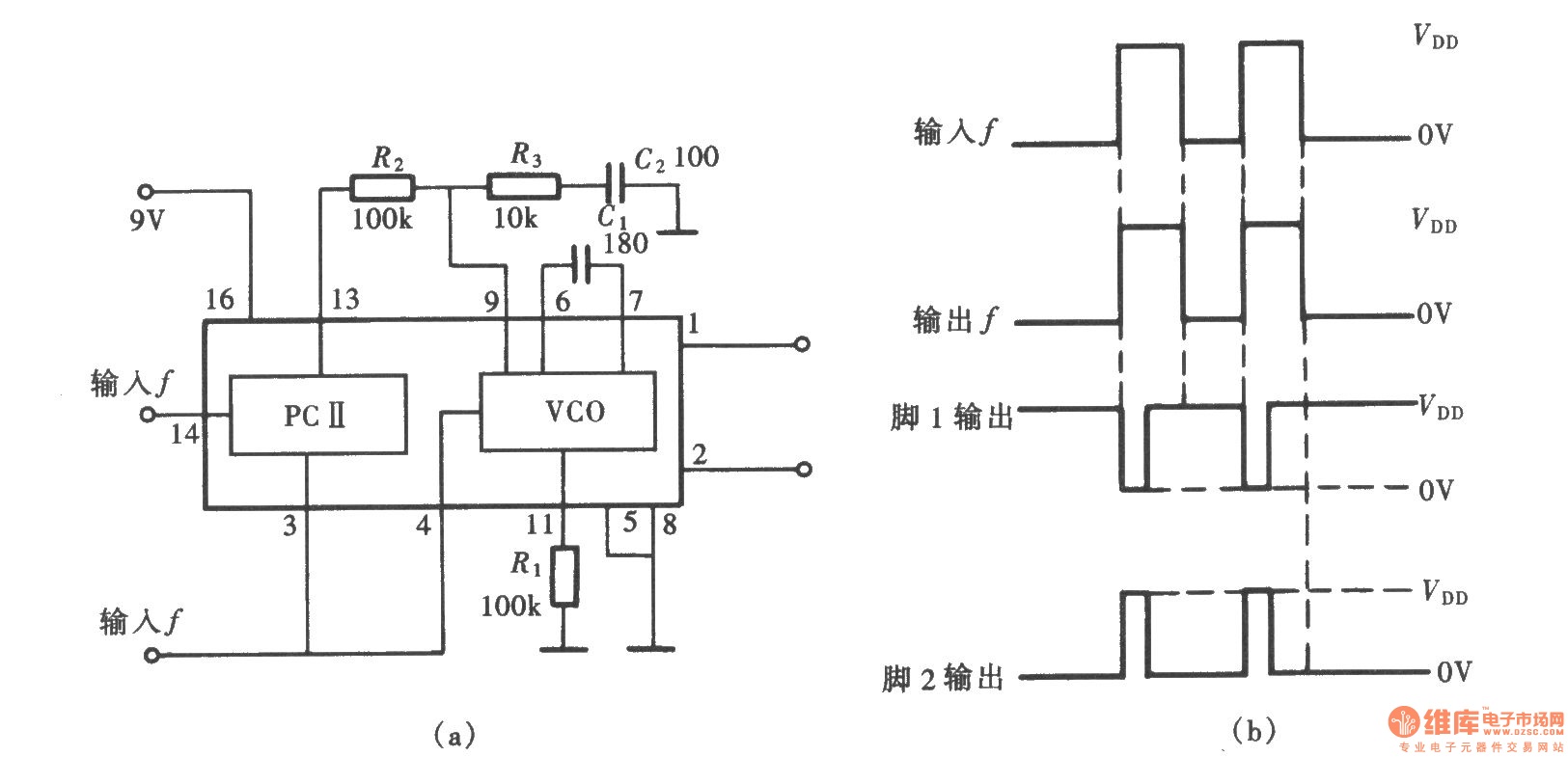
A frequency signal tracking circuit is implemented using a phase-locked loop (PLL) configuration, which is a fundamental application of the CD4046 integrated circuit. The circuit, illustrated in the accompanying chart, utilizes the CD4046 to form a PLL that effectively...
Some good inverter circuits I found oscillate at approximately 50 to 60 Hz. They are likely capable of handling up to two amps; any more than that will cause them to automatically shut off. If there are questions, please...