
Testatika Free energy

However, this may not be a waste of extra potential. It is suggested that the main power output does not solely come from what the two contra-rotating discs supply. There is a belief that a more significant power generator, the electron cascade generator, exists within the two horseshoe magnets. If the circuits to the magnets are made to oscillate at the right frequency at a high enough voltage, these metalized-perspex laminated blocks can generate a much larger amount of electricity than is input into them.
The description indicates that between the horseshoe magnet legs are four blocks of transparent 'plexiglass' type material alternated with copper and aluminum plates, arranged in a specific sequence. According to the Linden Experiment, where resonance of about 80-140 MHz is induced in a coiled horseshoe, a voltage could be taken off the plates of the block which measured 700 volts (DC presumably). This phenomenon has not been replicated by any outside researcher and is considered fundamental to understanding the Methernitha machine's operation.
The electron cascade or avalanche effect occurs when air molecules are accelerated to such high velocities that they collide with other molecules, liberating new electrons that further collide and liberate even more free electrons. This chain reaction is a natural phenomenon, also observed in lightning strikes, and results in the environment becoming part of the circuit. The process negatively ionizes the air surrounding the Methernitha machines, creating a cool and fresh atmosphere.
The design incorporates insulated wire, possibly bifilar, wound around the horseshoe metal, allowing for the extraction of additional electric current produced directly from the electron cascade blocks. Suitable connections may lead down into the wooden base, where it is believed that a layered structure of perforated metal plates and insulating plates forms a large high-voltage storage capacitor. This power could be discharged as a pulsed output of high wattage, especially if configured as a Pulse Forming Network.
The two large cans are likely not highly technical; once the fundamental formula has been established, all models of a Testatika generator would follow a similar construction process. Descriptions suggest a central input rod or tube connecting to a stack of inter-linked pancake coils, wound secondary-outside primary-inside, fitted around a core of hollow donut-ring magnets. The output of each can connects from the top coil of the secondaries of the pancake coils to a brass ring around the center of the lid. The arrangement of the magnets is designed to prevent the magnetic flux fields of the pancake primaries from merging, allowing each pancake's magnetic flux to cut its own adjoining secondary coil, thus reducing reliance on complex insulating procedures associated with high-voltage transformers.
The use of aluminum mesh and solid copper sheeting is common in electronic construction. The outer aluminum mesh cylinder shields stray electrostatic charges, while the solid copper cylinder shields stray electromagnetic fields produced during the transformation process from high voltage/low current to lower voltage/higher current. The red-wired can's transformer is wired to output negative, while the blue-wired can's transformer outputs positive polarity. This arrangement is reminiscent of similar designs by Van de Graaff in high-voltage electromagnetic charged-particle accelerator apparatus.The Testatika design based on the Pidgeon/Wimshurst machine is of course only one type of electrostatic generator to build this system around. Since the early 1900s such power generators have come a long way in sophistication - and in power output - recently developed machines output 300,000 volts which can then be transformed and utilized
After reading through the many early accounts of electrostatic rotary machines, and some of the more recent ones, you can't help but be puzzled by the Methernitha's incredibly low rotational speed of just 60 rpm (and in the 1999 engineers report as low as¦15 rpm !). Most other early experimenters boasted up to 3000 rpm, J.G.Trump in his work on high voltage generation in space [note 12] spun his rotary machine at 10,000 rpm (to produce 433 Watts at 24 KV no less).
One reason for this low speed might be to do with the close proximity of the 50 lamellas (gitter-grilles) on the discs at their inner ends, they are very close together, I think too close. Air, normally an insulator, breaks down and conducts at around 25-35 KV (this figure has been fairly constant from day-one of electrostatic machine experiments right through to the present day because air has a breakdown field strength of 3x10⁶ volts/metre) and short-circuits the circuit.
I feel that because this design of grilles is prone to short-circuiting at high voltages the Methernitha people have limited their rotational speed so as to ensure a low operating voltage of what I'd guesstimate to be only 12 to 24KV. But, is this a waste of extra potential ? Not necessarily¦For I don't think that the main power output comes solely from what the two contra-rotating discs supply.
There is, I believe, a far more important power generator¦the electron cascade generator, and the Methernitha has two of them, held inside the two horseshoe magnets, and providing the circuits to the magnets are made to oscillate at the right frequency at a high enough voltage then these metalised-perspex laminated blocks can enmass A MUCH LARGER AMOUNT OF ELECTRICITY THAN WHAT IS PUT INTO THEM. This, perhaps, is the previously unknown electronic phenomenon that the Methernitha group have so zealously been trying to protect against unscrupulous entrepreneurs.
But I would say that this copious supply of free energy is already known to the world - it is not readily available - and its principles are not fully understood, as yet, but it is known about. As the descriptions say (on the Testatika website), between the horseshoe magnet legs are four blocks of transparent 'plexiglass' type material alternated with copper and aluminium plates (that may or may not be perforated), in the sequence c-p-a-c-p-a-c-p-a-c-p-a (also see fig.6).
And according to the Linden Experiment, where Paul Baumann induces a resonance of about 80-140 MHz in a coiled horseshoe and then has an aluminium-insulator-copper block moved between the horseshoe legs, a voltage could be taken off the plates of the block which measured 700 volts (DC presumably) [note 13]. This incredible phenomenon has never been replicated by any 'outside researcher', and is said to be the basis by which the Methernitha machine could be understood how to work [the clue, possibly, to this principle may be variable-capacitance and dielectric-absorpsion].
But what, I hear you say, is an electron cascade... Well, it was only by chance, very recently, that I happened to listen to an audio tape by a Dr. Flanagan about crystal water; when I switched the tape over after the end of side one Dr. Flanagan then began talking about an electronic configuration that applied a high frequency, high voltage alternating field across an insulator that created what he called an electron cascade effect Yes, I thought, here is the answer to the Methernitha Machine. The electron cascade or avalanche effect is where air molecules are accelerated to the device at such a high velocity that they collide with other molecules and atoms in the air to liberate new electrons which in turn also collide and liberate even more 'free electrons' from other air molecules (see fig.5), all of which become accelerated by the electric field, and an avalanche of electron-multiplications progresses throughout the whole immediate environment [note 14].
It's a chain reaction, and an entirely safe one, it happens in a more ferocious way in lightning strikes, and is a natural phenomenon. And, as in this case, the environment actually becomes part of the circuit [note 15] because the process is actually negatively-ionising the air surrounding the Methernitha machines, and that is why those who have been near these generators when working say the air around about them is cool and fresh [note 16].
In view of the fact that it's designers have chosen to wind insulated wire (which may be bifilar [note 17]) around the horseshoe metal [note 18], it would be very possible to draw the extra electric current produced directly from the electron cascade blocks, with suitable connections that might lead downward into the wooden base (where it is believed that an alternate layering of perforated metal plates and insulating plates - making up a large high-voltage storage capacitor - is located). This power could then be discharged as a pulsed output of high wattage, especially if configured as a Pulse Forming Network [note 18].
The two big cans at the side, are probably not highly technical (see fig.7), once the fundamental formula has been decided upon all models of a testatika generator would follow a similar construction process. The written descriptions are a little contradictory but they seem to suggest a central input rod, or tube, connecting at the bottom of the cans to a stack of inter-linked pancake coils, that are wound secondary-outside primary-inside, fitted around a core of 6 hollow donut-ring magnets stacked in such a way with plastic spacers as to allow air gaps between them, and then finally the output of each can is a connection from the top coil of the secondaries of the pancake coils to a brass ring around the centre of the black plastic top lid and from the photographs can be seen a large diameter wire or tube [note 19] connecting that polarity's output terminal to the top lid's brass ring via a brass screw terminal.
I would suggest that the ring magnets (of anistropic ferrite perhaps) are gapped in this way to prevent the magnetic flux fields of the pancake primaries co-joining as one sprawling field, because it would be more advantageous, and safer, to have each separate pancake's magnetic flux cut it's own adjoining secondary coil, and divide the secondary output voltage into smaller amounts of potential, thus depending less on complicated insulating procedures that accompany high voltage single primary / single secondary transformers. The use of aluminium mesh and solid copper sheeting is commonly used in electronic construction; the outer aluminium mesh cylinder would be used to shield stray electrostatic charges, and the solid copper cylinder is to shield the large amount of stray electromagnetic fields produced by the transforming process from high voltage/low current to lower voltage/higher current [note 20], obviously they don't want field contamination taking place between the sensitive electrostatic generator and the transformers.
In the red wired can the transformer is wired to output negative, and the blue wired can's transformer is wired to output positive polarity. Special note should be made of a similar arrangement devised by Van de Graaff in his 'High Voltage Electromagnetic Charged-Particle Accelerator Apparatus Having an Insulating Magnetic Core' [note 21] with respect to magnetic reluctance gaps.
🔗 External reference
Related Circuits
Here's something that has always bugged me: light waves are about 5000 Angstroms in wavelength, while atoms are more like 1 Angstrom across. Atoms are thousands of times smaller than light waves, yet atoms obviously interact very strongly with...
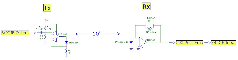
This article aims to illustrate a basic optical LED wireless link for transmitting high-definition (HD) S/PDIF digital audio streams. Circuit designs for both the transmitter (optical modulator) and receiver are provided, utilizing cost-effective op-amp configurations. Specific components are listed,...
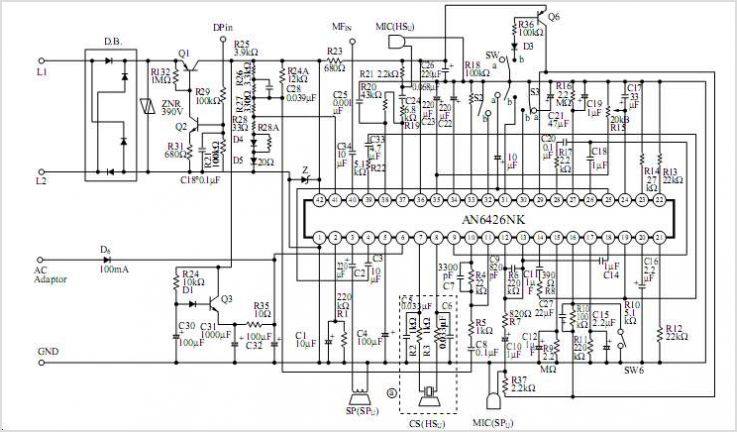
AN6591FJM is a single-chip integrated circuit (IC) optimized for Personal Handy-phone System (PHS) applications. It integrates a quadrature modulator for reception intermediate frequency (IF) and a phase-locked loop (PLL). The IC is housed in a quad flat non-leaded (QFN)...
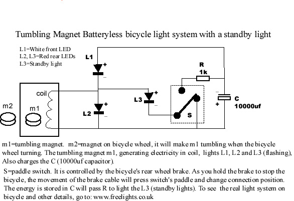
This bicycle safety flashing light system is based on a newly invented electrical generation system that requires no battery and produces no friction on any parts of the bicycle. It generates energy with minimal resistance, making it highly efficient...
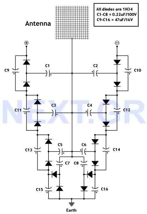
This circuit converts surrounding radio frequency waves to electric power. It can provide 40 Volts at 10 Watts indefinitely. The output power can be improved by adjusting the antenna. Placing the antenna near large metal objects increases power. The...
Every innovation begins with a simple everyday problem, such as watching an IPL match on TV when suddenly the power goes out, prompting the search for an alternative way to watch via mobile network. Similarly, a frequent issue of...