
The AA8V/W8EXI 6CL6 One-Tube Transmitter
The circuit can be modified by relocating the RF ground point from the cathode to the screen grid (plate) of the tube and adding a key. The 0.005µF screen bypass capacitor grounds the screen grid for RF while preventing the DC screen voltage from being shorted to ground. The RF choke is repositioned to the cathode lead, allowing the cathode to float above ground for RF. Aside from the ground point relocation and key addition, this circuit remains identical to the previous one and to the configuration used in the 6CL6 transmitter.
However, a notable issue with this circuit is the lack of an apparent output connection, which may give the impression that it oscillates without producing a useful signal. In reality, it generates an RF signal on the control grid of the tube. By applying a positive voltage to the actual plate of the tube and drawing current from it, this current can be controlled by the signal on the control grid, resulting in an amplified signal on the actual plate. Thus, the circuit simultaneously oscillates and amplifies using the same tube.
In summary, the screen grid, control grid, and cathode function as a grounded screen (plate) crystal oscillator, while the cathode, control grid, and actual plate serve as an amplifier. The control grid acts as the common element in both circuits, coupled through the common electron stream within the tube. This coupling is why the circuit is referred to as an "electron-coupled oscillator." A significant advantage of this design is that the grounded screen grid effectively shields the plate output circuit from the oscillator circuit, ensuring excellent isolation between the two, particularly when utilizing a well-shielded tube like the 6CL6.
Without the electron-coupled circuit, tuning and load adjustments significantly impact oscillator operation and keying, potentially halting oscillation at certain tuning and load settings. In contrast, the electron-coupled circuit minimizes the influence of tuning and load controls on the oscillator, enhancing stability and keying performance, especially with well-shielded tubes like the 6CL6. All oscillators require feedback from the output to the input for proper operation. While tube inter-electrode capacitances may suffice, they can vary between tubes. Therefore, using external capacitors to establish the feedback path and compensate for tube capacitances is advisable. In this circuit, the 0.005µF screen bypass capacitor effectively acts as a short circuit for RF, allowing the 220pF capacitor to connect the screen (oscillator plate) and cathode.The operation of the 6CL6 transmitter is actually quite sophisticated, despite the simple appearance of the circuit. The heart of the circuit is the electron-coupled crystal oscillator shown above. This circuit combines the functions of oscillator and amplifier into a single tube, and provides excellent isolation between the oscillator and the out
put circuit. To understand the operation of an electron-coupled oscillator, consider first the triode oscillator shown below: In this circuit the cathode is grounded and the screen grid of the tube is being used as the plate. (It is perfectly fine to use the screen grid as the plate, as long as the input is kept low enough so that the screen grid isn`t damaged.
) Feedback is obtained via the grid-plate capacitance of the tube and the 22pf and 220pf feedback capacitors. The crystal controls the frequency of oscillation. Rectified grid current through the 68k resistor provides bias for the tube. In this circuit, note that the cathode is grounded for RF and the plate (screen grid) is above ground for RF.
The RF choke and bypass capacitor allow us to feed DC voltage to the screen while preventing the RF on the screen from getting into the power supply. Let us now modify the previous circuit by moving the ground point for RF from the cathode of the tube to the screen grid (plate) of the tube and by adding a key, as shown in the circuit below: The.
005uf screen bypass capacitor grounds the screen grid (plate) for RF while preventing the DC screen voltage from being shorted to ground. Meanwhile, the RF choke has been moved to the cathode lead so that the cathode can now float above ground for RF.
Except for moving the ground point and adding the key, this circuit is identical to the previous. It is also identical to the circuit in the 6CL6 transmitter. The problem with the above circuit is that there is no apparent output connection. It just appears to oscillate without doing anything useful! In reality, however, it is doing something very useful: it is producing an RF signal on the control grid of the tube. If we now apply a positive voltage to the real plate of the tube and draw current from the real plate of the tube, this current will be controlled by the signal on the control grid, and an amplified signal will appear on the real plate of the tube.
Thus, the circuit oscillates and amplifies using the same tube! In summary: The screen grid, control grid, and cathode are used as a grounded screen (plate) crystal oscillator, while the cathode, control grid, and real plate are used as an amplifier. The control grid is the common element in the two circuits, and they are only coupled by the common electron stream within the tube.
This is why the circuit is known as an "electron-coupled oscillator". The big bonus of this circuit is that the grounded screen grid shields the plate output circuit from the oscillator circuit, providing very good isolation between the two, especially when a well screened tube such as the 6CL6 is used. Without the electron-coupled circuit, tuning and load adjustments have a big effect on oscillator operation and keying, to the point that oscillation may actually stop at some settings of the tuning and load controls.
With the electron-coupled circuit the impact of the tuning and load controls on the oscillator is greatly reduced. This means much better stability and keying, especially when a well screened tube, such as the 6CL6, is used.
All oscillators require feedback from the output to the input to operate. Tube inter-electrode capacitances are often sufficient, but can vary from one tube to the next. As a result, it is best to use external capacitors to provide the feedback path and swamp the tube capacitances. In this circuit, the. 005uf screen bypass capacitor is essentially a short circuit for RF, and thus the 220pf capacitor is essentially connected between the screen (oscillator plate) and catho
🔗 External reference
Related Circuits
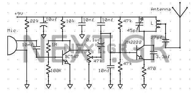
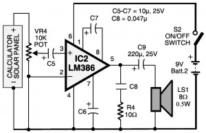
This transmitter can be powered by a 9V battery (not exceeding 12V). Users can connect a music source at the microphone input or utilize a simple condenser microphone. The signal range can reach up to 400 meters in open...

The ADC12038 family consists of 12-bit plus sign sampling Analog-to-Digital Converters (ADCs) featuring serial input/output. These devices are equipped with configurable analog multiplexers that can accommodate 2, 4, or 8 input channels. Upon request, these ADCs can execute a...
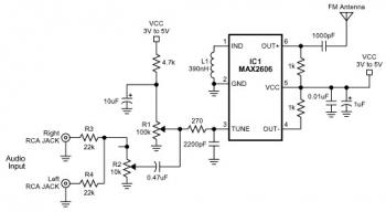
The FM transmitter circuit is built using a single MAX2606 chip. This simple FM transmitter connects a home entertainment system to a portable radio, allowing music to be played in one room and listened to in another, such as...
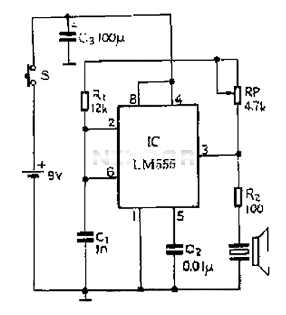
A 40 kHz ultrasonic transmitter circuit utilizes the LM555 timer as a time base circuit along with external components to create a 40 kHz multivibrator. The resistance of the adjustable resistor RP can modify the oscillation frequency. The output...
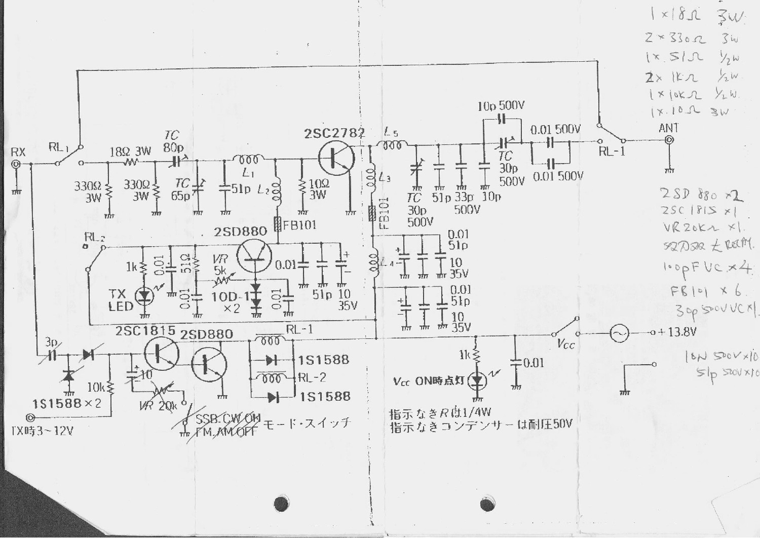
This is a 6-meter band transmitter RF power amplifier designed for 50 MHz operation, delivering an output power of 100 watts. It is intended for use with the FT-736R transceiver and is driven by a 10-watt signal for 6-meter...
This circuit diagram represents a laser communication system that transmits sound or music signals using a laser beam. The intensity of the laser beam varies in accordance with the amplitude of the sound signal. This variation in laser intensity...