
100W Transmitter RF Power Amplifier 2SC2782
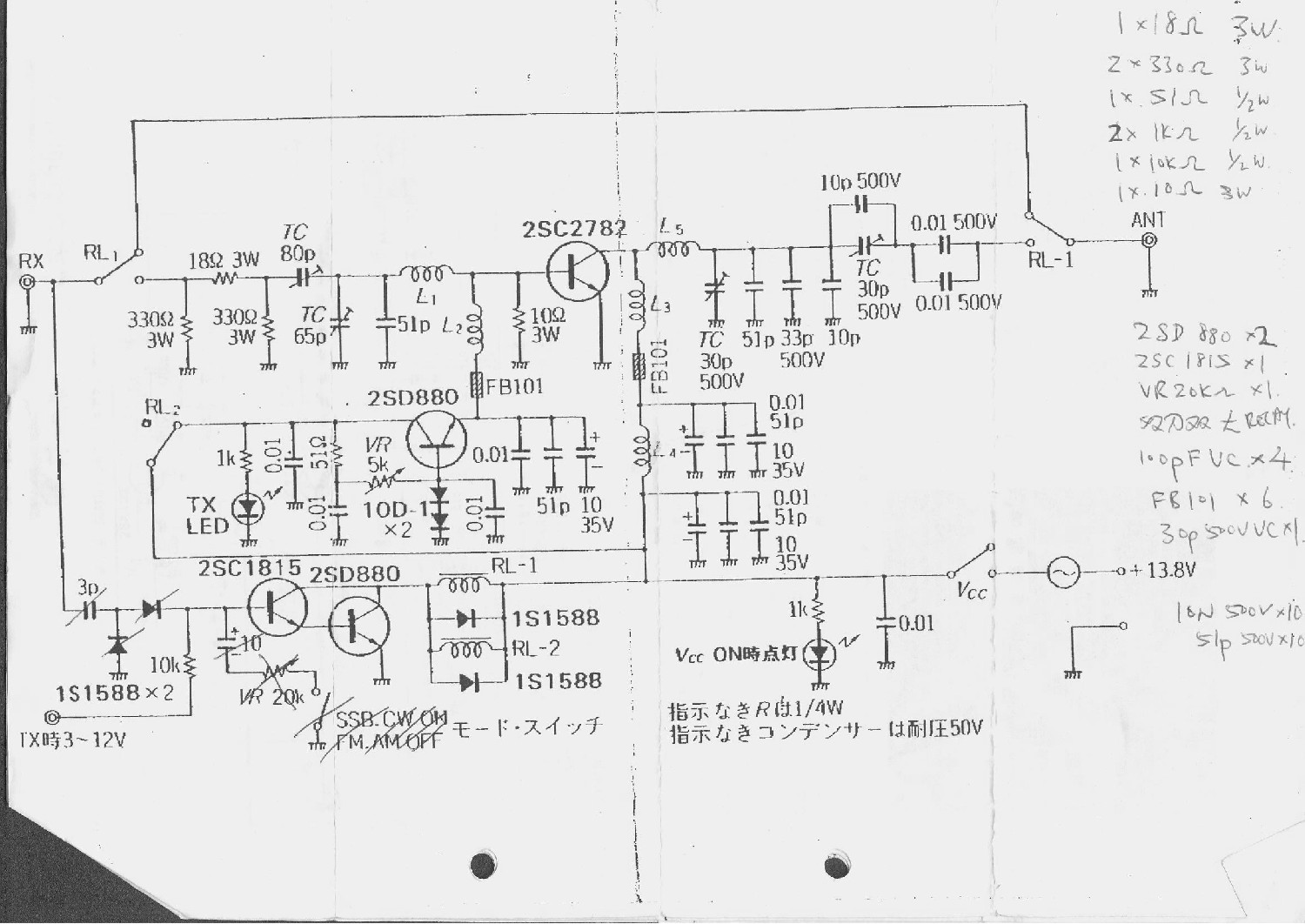
The 6-meter band RF power amplifier circuit is designed to amplify signals in the VHF range, specifically at 50 MHz, which is commonly used for amateur radio communications. The amplifier operates on a class of operation that typically favors efficiency and linearity, which is crucial for SSB (Single Sideband) transmission.
The choice of a Toshiba RF bipolar power transistor is significant due to its reliability and performance characteristics in RF applications. Bipolar transistors provide high power gain and are capable of handling the necessary output power levels. When designing the circuit, careful consideration should be given to the transistor's biasing to ensure optimal performance and prevent thermal runaway.
Utilizing a double-sided PCB layout is advantageous for this amplifier design. This configuration allows for better grounding techniques, which is critical in RF applications to minimize noise and interference. The double-sided layout also facilitates the routing of power and ground planes, improving current transfer and thermal management.
The amplifier's output power can be tuned to reach up to 120 watts, providing flexibility for various operational conditions. This tuning capability is typically achieved through adjustable components in the circuit, such as variable resistors or capacitors, enabling the user to optimize performance based on specific requirements or conditions.
In conclusion, this 6-meter band RF power amplifier is a robust design suitable for amateur radio enthusiasts looking to enhance their signal strength for SSB communications. Proper construction techniques, including the use of a double-sided PCB and careful component selection, are essential for achieving the desired performance levels.This is a 6m band transmitter RF power amplifier (50 MHz) with 100W output. It used with my FT-736R and drive from 10W for the 6m SSB DX. The Building information comes from Japan CQ Magazine. The Toshiba RF bipolar power transistor is used in it. If you want to construct this rf amplifier, it`s the better way if the double side PCB use for increase the grounding and current transfer. The TX power can be tune to 120W 🔗 External reference
Related Circuits

The genesis for this hybrid electrostatic headphone amplifier occurred when I was in Hawaii on vacation, at a fancy hotel on Maui. Sitting at the bar on the beach, drinking "Blue Hawaiis," I drew the schematic for the amp...
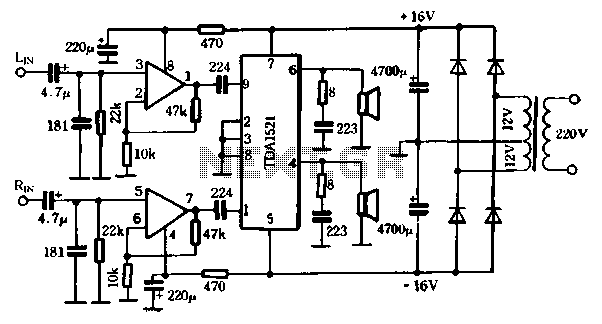
The first power amplifier circuit illustrated in Figure 5-88 utilizes the NE5532 operational amplifier, configured as a line amplifier, and features the TDA1521 power amplifier. This circuit operates with a dual power supply and eliminates the need for coupling...
V1 and V2 are set to 5V in the simulation, but they could also be set to 10V to eliminate the need for a second power supply. Alternatively, if logic level FETs can be sourced at that higher voltage,...

This circuit exhibits an exceptionally fast high-frequency response, as demonstrated by applying a 100 kHz square wave to the input. All graphs were produced using Tina Pro. The circuit's design is optimized for high-frequency applications, showcasing rapid response times that...
This project originated from a design requirement for a client, specifically for a microphone preamplifier intended for basic public address (PA) systems. The simplicity of this circuit makes it suitable for various applications where a mic preamp is needed,...
This design adopts a well established circuit topology for the power amplifier, using a single-rail supply of about 60V and capacitor-coupling for the speaker(s). The advantages for a guitar amplifier are the very simple circuitry, even for comparatively high...
Warning: include(partials/cookie-banner.php): Failed to open stream: Permission denied in /var/www/html/nextgr/view-circuit.php on line 713
Warning: include(): Failed opening 'partials/cookie-banner.php' for inclusion (include_path='.:/usr/share/php') in /var/www/html/nextgr/view-circuit.php on line 713